
User's Manual


Product user manual & operation description
EMV3000
Document number: 915-11135-01 Page 20 | 26
6 INSTALLATION INSTRUCTIONS
6.1 EMV3000 mechanical integration
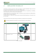
1. The EMV3000 back shell contains 3 mounting holes (3 inserts M2.5) (Figure 4). These mounting
holes can be used to fix the EMV3000 to a mounting frame. Mounting frames are project specific
but can be ordered at Emsyscon.
The maximum screw length mounted into the EMV3000 is 6mm. This based on a mounting frame
with 2mm thickness. Depending on the mounting frame thickness, the screw length must be
adapted by the installer.
Figure 3: Mounting holes
3 inserts M2.5