
Installation manual

EMS 5000 FIREPOINT
8
INSTALLATION MANUAL, ISSUE 3.0 – 16/08/10
11. Installation Advice.
Ensure that you have all equipment required to complete the installation of 5000
FirePoint.
Ensure that the correct fixings and fasteners are used for all installation work.
Observe ESD precautions.
Familiarise yourself with the system details and layout, before commencing any
installation activity. Any anomalies must be addressed with the Surveyor, End user or
the equipment supplier.
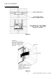
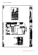
Ensure that the Control Panel back box is clean and free of swarf prior to fitting the
internal assemblies.
Also ensure that aerials are fitted with anti tamper cones before applying 230V to the
control panel.
The 240V power supply to the Control Panel must be made by way of an individual fused
spur, situated adjacent to the Control Panel. The fused spur must have it’s own power
supply circuit fitted with a 3 Amp fuse. Affix a red circuit breaker, labelled “Fire Alarm,
Do Not Switch Off”, to the circuit. It is recommended that the circuit breaker be secured
from unauthorised access. The fused spur should be similarly labelled as “Fire Alarm”.
Wherever practical, fix detectors so that the red LED faces the main entrance to the
room.
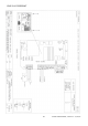
Should it be necessary to remove the two aerials fitted to the Control Panel, ensure that
when refitted, the coloured band on the aerial corresponds with the coloured disk on the
BNC connector on the panel.
Ensure that the 240V AC mains supply is fused and unswitched.