
Installation manual

EMS 5000 FIREPOINT
7
INSTALLATION MANUAL, ISSUE 3.0 – 16/08/10
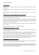
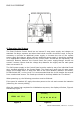
When the Control Panel is first powered up, the “General Fault” LED will illuminate and
the fault buzzer will sound. This continues whilst the system initialises itself and runs
through self-test routines.
Once initialised, the green “Power” LED will illuminate. At this time the “General Fault”
LED will also be illuminated, whilst the display will indicate a “PR” fault. Press “SILENCE
ALARM” followed by “RESET” to clear this LED. The Control Panel will run through a
series of diagnostic self tests. The illumination of the applicable LED and the sounding of
the fault buzzer will indicate any errors on the display.
Under normal non fault conditions, the display will indicate status as “Normal” (see
Figure 6). If the Key Switch is left in the “On” position, the display will indicate that the
panel is in “Access mode” (see Figure 7).
Figure 6 Figure 7
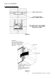
10. External Wiring
10.1 Hardwired Sounder
The 5000 FirePoint Control Panel includes provision for two hardwired sounder circuits.
The circuitry monitors two pairs of conductors fitted with 4k7 End of Line resistors. No
connection to the control Panel should be made at this stage. The maximum current
permitted is 250mA per circuit.
10.2 Hardwired Call Point
The 5000 FirePoint Control Panel includes provision for a hardwired Call Point interface.
The Control Panel monitors this input via a 4k7 End of Line resistor. No connection to the
Control Panel should be made at this stage.
Note: The external connections & wiring must be tested in the conventional manner.
Under no circumstances should the system circuitry be tested using a meggar tester,
once the connections to the control panel, or peripherals, has been made.
10.3 Device Wiring
Using an Ohmmeter, check both sounder circuits to ensure that they have a 4.7k ohm
resistance across the connections and that the resistance between each connection and
the Control Panel earth point is greater than 20 M Ohm.
Check any Call Point external wiring. The resistance across the Call Point connection
should read 4.7k. Ensure that the resistance between each connection and the Control
Panel earth point is greater than 20 M Ohm.
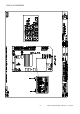
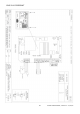
Once external wiring circuits have been checked, make the connections to the control
panel. The Control Panel should be powered down prior to termination. Connect all
external wiring to the applicable Control Panel terminals (see drawing p02910). Upon
completion of this, re-power the Control Panel.
EMS FIRE SYSTEMS LTD
Panel in Access
0 FOR ACCESS TIME
EMS FIRE SYSTEMS LTD
Status Normal
DATE TIME