
Installation manual

EMS 5000 FIREPOINT
6
INSTALLATION MANUAL, ISSUE 3.0 – 16/08/10
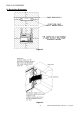
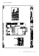
Figure 3
9. Powering the System
The 5000 FirePoint Control Panel has an internal 3 amp power supply and charger as
standard. On larger systems and where hard-wired sounder circuits are used, it may be
necessary to provide an additional power supply or increase the size of the system
power supply and charger. When using an additional power supply, it should be mounted
in an appropriate cabinet adjacent to the control panel. Should this be impractical, the
maximum distance between the Control Panel and power supply/charger should not
exceed 3 metres. Ensure that the voltage drop between the supply and the main panel
does not exceed 0.5v.
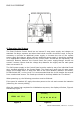
The 240V power supply to the Control Panel must be made by way of an individual fused
spur, situated adjacent to the Control Panel. The fused spur must have it’s own power
supply circuit fitted with a 3 Amp fuse. Affix a red circuit breaker, labelled “Fire Alarm,
Do Not Switch Off”, to the circuit. It is recommended that the circuit breaker be secured
from unauthorised access. The fused spur should be similarly labelled as “Fire Alarm”.
When powering up, the following procedure must be followed.
If the panel is switched off, apply the mains power to the unit and connect the batteries
(observing the correct polarity).
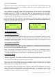
After the system has completed its initialisation sequence, the display will show, Figure 4
followed by Figure 5
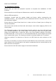
Figure 4 Figure 5
Searching
. . . . . . . . . .
01 02 03 04 05 06
Warm Start
FIRIS OS V1.6