
Installation manual

EMS 5000 FIREPOINT
39
INSTALLATION MANUAL, ISSUE 3.0 – 16/08/10
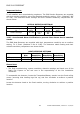
Sw
1
Sw
2
Sw
3
Sw
4
Sw
5
Sw
6
Sw
7
Heat
Band
Optical
Sensitivity
Off Off Off Off Off X Off 58ºC Normal
On Off Off Off Off X Off 58ºC Medium
Off On Off Off Off X Off 58ºC Low
On On Off Off Off X Off 58ºC Low+AVF
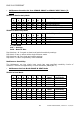
Sw
1
Sw
2
Sw
3
Sw
4
Sw
5
Sw
6
Sw
7
Heat
Band
Optical
Sensitivity
Off Off On Off Off X Off 72ºC Normal
On Off On Off Off X Off 72ºC Medium
Off On On Off Off X Off 72ºC Low
On On On Off Off X Off
72ºC
Low+AVF
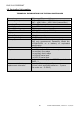
X – Not Used
AVF – Average
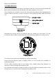
Algorithm 1 Characteristics: If there is an increase in heat detection, the algorithm will
set the optical sensitivity setting one level higher. I.e. the optical detector becomes more
sensitive.
Algorithm 2 Characteristics: If there is no increase in heat detection, the algorithm will
set the optical sensitivity setting one level lower. I.e. the optical detector becomes less
sensitive.
Dip Switches 1 & 2 remain as heat level/optical sensitivity settings
Dip Switch 3 will control the heat/optical sensitivity band.
Dip Switches 4 & 5 are both ON or both OFF For Algorithms 1 or 2.
Dip Switch 7 is OFF compatibility mode disabled.
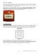
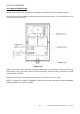
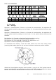
To reassemble the detector, locate the head section into the fixed ceiling mount
(ensuring that locating lugs line up) and turn clockwise to achieve a positive location.
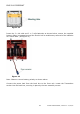
Figure 19
Within the Volume/Option switches, switch number 1, when in the “ON” position sets the
tamper to disabled. However flicking the switch to the “OFF” position enables the tamper
feature. This would be set before the device is set into it’s final location.