
Installation manual

EMS 5000 FIREPOINT
34
INSTALLATION MANUAL, ISSUE 3.0 – 16/08/10
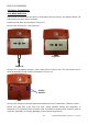
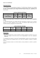
12.3 Radio Detectors
Ensure that all Detectors are sited in accordance with the survey and design details and
that, wherever practical, the red LED faces the main entrance to the room.
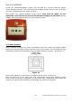
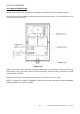
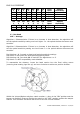
If the Detectors are complete, remove the ceiling mounting plate by first disengaging the
detector head by turning it counter clockwise. This exposes the Radio PCB (see Figure
14).
Figure 14
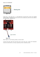
Disengage the ceiling mount by pressing down the locking pin (see Figure 15) and
turning the radio module counter clockwise whilst pushing it against the ceiling mount.
Figure 15
The ceiling mount will now be available for fixing to the ceiling.
Ensure that the Detector head is suitably stored so as to prevent the possibility of
accidental damage.
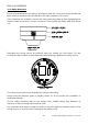
Fix the ceiling mounting plate to the ceiling using suitable fixings and fasteners. A
minimum of two mounting holes must be used.
It is important that fastener heads are flush or sub-flush with the internal surface of the
ceiling mount, to avoid the risk of damaging the battery PCB.