
Installation manual

EMS 5000 FIREPOINT
32
INSTALLATION MANUAL, ISSUE 3.0 – 16/08/10
Locate the Transmitter/Battery section into the back box, ensuring that the tamper
switch operates correctly. The switch should also make contact with the rear of the back
box/wall. (Established by the switch “clicking”).
Now replace the internal assembly fixing screws. Care must be taken, as over
tightening of the screws can prevent the element dropping on activation. Finally,
reapply the element and fix the front cover back into place.
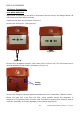
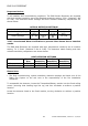
12.2 Radio Sounder
Ensure that all sounders are sited in accordance with the survey and design details.
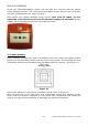
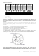
Remove the two assembly screws from the front of the sounder. This will allow the main
Transmitter section to be separated from the Battery/Back box section. (See Figure 11).
Figure 11
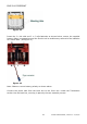
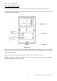
Remove the batteries to expose the mounting holes as shown in Figure 12.
Affix the back box to the wall using no.8 countersunk screws with suitable fixings.
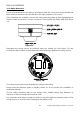
Ensure that the Sounder orientation is correct and that countersunk head screws are
used so as to prevent the possibility of damaging the internal components.