
Installation manual

EMS 5000 FIREPOINT
31
INSTALLATION MANUAL, ISSUE 3.0 – 16/08/10
12 Device Installation
12.1 Radio Call Point
Ensure that all Call Points are sited in accordance with the survey and design details. All
Call Points must be surface mounted.
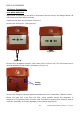
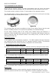
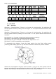
Insert the Call Point key as shown in Figure 8.
Remove the front cover. (See Figure 9).
Figure 9
Figure 8
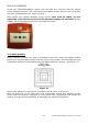
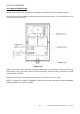
Remove the resettable element. (Also retain this for future use) This will expose the 2
internal assembly fixing screws (as shown in Figure 10).
Figure 10
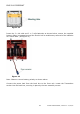
Remove the fixing screws and separate the back box from Transmitter / Battery section.
Mount the back box 1.4m from the floor, using suitable fixings and fasteners. A
minimum of 2 mounting holes must be used. Countersunk head screws must be used to
avoid the possibility of causing damage to the internal components.
Fixing
Screws