5000 INSTALLATION MANUAL
EMS 5000 FIREPOINT Table of Contents Section Page No 1. INTRODUCTION ................................................................................................ 3 2. WARNINGS AND CAUTIONS ............................................................................... 3 3. UNPACKING ..................................................................................................... 3 4. INSTALLATION .................................................................................................
EMS 5000 FIREPOINT 1. Introduction This manual provides an installation guide to the EMS 5000 FirePoint, Fire Control Panel and peripheral devices. It is important that for correct installation, the instructions given in this manual are followed. Should you have any questions regarding the installation of the System 5000, please ring our technical Helpline No 08712 710804 (0800-1800 MonFri), or alternatively your regional technical support representative.
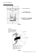
EMS 5000 FIREPOINT 4. Installation Following the Site Survey, System Control Panels should be positioned as stated considering:The recommended minimum distance between metal objects or equipment for the aerial is 400mm. The recommended minimum distance to any electrical equipment is 2 metres, (See Figure 1). 5. Control Panel - Removing Items before Mounting Before mounting the unit, it is necessary that certain items be removed, so as to prevent the risk of damage to the internal circuitry.
EMS 5000 FIREPOINT 8. Mounting Diagrams Figure 1 Figure 2 5 INSTALLATION MANUAL, ISSUE 3.
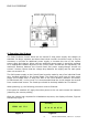
EMS 5000 FIREPOINT Figure 3 9. Powering the System The 5000 FirePoint Control Panel has an internal 3 amp power supply and charger as standard. On larger systems and where hard-wired sounder circuits are used, it may be necessary to provide an additional power supply or increase the size of the system power supply and charger. When using an additional power supply, it should be mounted in an appropriate cabinet adjacent to the control panel.
EMS 5000 FIREPOINT When the Control Panel is first powered up, the “General Fault” LED will illuminate and the fault buzzer will sound. This continues whilst the system initialises itself and runs through self-test routines. Once initialised, the green “Power” LED will illuminate. At this time the “General Fault” LED will also be illuminated, whilst the display will indicate a “PR” fault. Press “SILENCE ALARM” followed by “RESET” to clear this LED.
EMS 5000 FIREPOINT 11. Installation Advice. Ensure that you have all equipment required to complete the installation of 5000 FirePoint. Ensure that the correct fixings and fasteners are used for all installation work. Observe ESD precautions. Familiarise yourself with the system details and layout, before commencing any installation activity. Any anomalies must be addressed with the Surveyor, End user or the equipment supplier.
EMS 5000 FIREPOINT 9 INSTALLATION MANUAL, ISSUE 3.
EMS 5000 FIREPOINT 10 INSTALLATION MANUAL, ISSUE 3.
EMS 5000 FIREPOINT 11 INSTALLATION MANUAL, ISSUE 3.
EMS 5000 FIREPOINT 12 INSTALLATION MANUAL, ISSUE 3.
EMS 5000 FIREPOINT 13 INSTALLATION MANUAL, ISSUE 3.
EMS 5000 FIREPOINT 14 INSTALLATION MANUAL, ISSUE 3.
EMS 5000 FIREPOINT 15 INSTALLATION MANUAL, ISSUE 3.
EMS 5000 FIREPOINT 16 INSTALLATION MANUAL, ISSUE 3.
EMS 5000 FIREPOINT 6-way connector PCB 2522 3648 H/W Receiver Module 17 INSTALLATION MANUAL, ISSUE 3.
EMS 5000 FIREPOINT 18 INSTALLATION MANUAL, ISSUE 3.
EMS 5000 FIREPOINT 19 INSTALLATION MANUAL, ISSUE 3.
EMS 5000 FIREPOINT 20 INSTALLATION MANUAL, ISSUE 3.
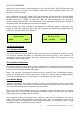
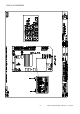
EMS 5000 FIREPOINT 230V Spur Fire Alarm Green band 5-5501 Typical Panel Layout Yellow band 5-5500 5-5024 1 INSTALLATION MANUAL, ISSUE 3.
EMS 5000 FIREPOINT 22 INSTALLATION MANUAL, ISSUE 3.
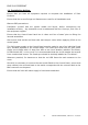
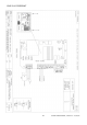
5-5500 Yellow Band EMS 5000 FIREPOINT Fire Alarm 230V Spur Fire Alarm RS 485 4 core Industry Standard Fire rated cable 230V Spur 5-5501 Green Band 5-5438 LAN Module 5-5501 Green Band Typical LAN Panel Layout Including LAN Module 5-5924 Note: All panels and aerials to be at least 2m apart Maximum cable run for RS485 Bus 1 Km 3 INSTALLATION MANUAL, ISSUE 3.
EMS 5000 FIREPOINT 24 INSTALLATION MANUAL, ISSUE 3.
EMS 5000 FIREPOINT Green Band 5-5501 230V Spur Fire Alarm Typical VHF Transponder Layout Yellow Band 5-5500 2m apart 5-5400 5 INSTALLATION MANUAL, ISSUE 3.
EMS 5000 FIREPOINT 26 INSTALLATION MANUAL, ISSUE 3.
EMS 5000 FIREPOINT Yellow Band 5-5500 Yellow Band 5-5500 Green Band 5-5501 Fire Alarm Green Band 5-5501 Fire Alarm 230V Spur RS485 4 core Industry standard fire rated cable 230V Spur 5-5024 Typical Hardwired Panel Network Layout 5-5023 Note: All panels and aerials to be at least 2m apart Maximum cable run for RS485 Bus 1 Km 7 INSTALLATION MANUAL, ISSUE 3.
EMS 5000 FIREPOINT 28 INSTALLATION MANUAL, ISSUE 3.
EMS 5000 FIREPOINT 5-5501 Green Band 5-5500 Yellow Band 5-5500 Yellow Band Fire Alarm 5-5501 Green Band Fire Alarm 230V Spur 4 core industry standard fire rated cable RS 485 230V Spur 5-5024 Typical Panel Layout including a VHF/UHF Transceiver 5-5415 Note: All panels and aerials to be at least 2m apart Maximum cable run for RS485 Bus 1Km INSTALLATION MANUAL, ISSUE 3.
EMS 5000 FIREPOINT 30 INSTALLATION MANUAL, ISSUE 3.
EMS 5000 FIREPOINT 12 Device Installation 12.1 Radio Call Point Ensure that all Call Points are sited in accordance with the survey and design details. All Call Points must be surface mounted. Insert the Call Point key as shown in Figure 8. Remove the front cover. (See Figure 9). Figure 9 Figure 8 Remove the resettable element. (Also retain this for future use) This will expose the 2 internal assembly fixing screws (as shown in Figure 10).
EMS 5000 FIREPOINT Locate the Transmitter/Battery section into the back box, ensuring that the tamper switch operates correctly. The switch should also make contact with the rear of the back box/wall. (Established by the switch “clicking”). Now replace the internal assembly fixing screws. Care must be taken, as over tightening of the screws can prevent the element dropping on activation. Finally, reapply the element and fix the front cover back into place. 12.
EMS 5000 FIREPOINT Figure 12 Insert the 3 x AA cells and 3 x C cells batteries as shown below, ensure the supplied battery ribbon is wrapped around the first AA cell to enable easy removal of the batteries at a future date. (As Figure 13). Figure 13 Note: Observe correct battery polarity as shown above. Connect the power lead from the back box to the front unit. Locate the Transmitter section into the back box, securing in place by the two assembly screws. 33 INSTALLATION MANUAL, ISSUE 3.
EMS 5000 FIREPOINT 12.3 Radio Detectors Ensure that all Detectors are sited in accordance with the survey and design details and that, wherever practical, the red LED faces the main entrance to the room. If the Detectors are complete, remove the ceiling mounting plate by first disengaging the detector head by turning it counter clockwise. This exposes the Radio PCB (see Figure 14).
EMS 5000 FIREPOINT Important Notice: To all installers and commissioning engineers. The EMS Smoke Detectors are supplied with their smoke sensitivity set to the standard sensitivity setting, 2.3%. (Switches 1 Off & 2 On). The detectors switch settings and their relevant sensitivity comparisons are shown below: Smoke Sensitivity % per M Switch Settings OPTICAL DETECTOR SETTINGS Level 1 Level 2 Level 3 High Std 2.3% Low 1.6% 3.0% 1 & 2 Off 1 Off 2 1 On 2 On Off Level 4 3.
EMS 5000 FIREPOINT 12.4 Input/Output Units Ensure that all I/O Units are sited in accordance with the survey and design details. Remove the two lid retaining screws situated on the front cover. The front section of the unit can now be removed. Figure 16 Offer the unit up to the wall and using the back plate as a template mark out the three fixing holes. The unit can be fixed to the wall and all external wiring connections made (see drawing P04242).
EMS 5000 FIREPOINT 12.5 Combined Sounder Sensors Ensure that all sounder sensors are sited in accordance with the survey and design details and that, wherever practical, the red LED faces the main entrance to the room. The sounder sensor is shown in Figure 17 and consists of two separate sections. The mounting plate is shown in Figure 18 and can be removed by turning the mounting plate whilst holding the sounder/sensor section.
EMS 5000 FIREPOINT • Multisensor Sounder Set Into SINGLE SMOKE or SINGLE HEAT Mode (55190) ZR432 In Smoke Only Mode Sw 1 Off On Off On Sw 2 Off Off On On Sw 3 Off Off Off Off Sw 4 On On On On Sw 5 Off Off Off Off Sw 6 X X X X Sw 7 Off Off Off Off Mode Of Operation Sw 5 On On On On Sw 6 X X X X Sw 7 Off Off Off Off Mode Of Operation High Sensitivity Normal Sensitivity Low Sensitivity Low Sensitivity + AVF ZR432 In Heat Only Mode Sw 1 Off On Off On Sw 2 Off Off On On Sw 3 Off Off Off Off Sw
EMS 5000 FIREPOINT Sw 1 Off On Off On Sw 2 Off Off On On Sw 3 Off Off Off Off Sw 4 Off Off Off Off Sw 5 Off Off Off Off Sw 6 X X X X Sw 7 Off Off Off Off Heat Band 58ºC 58ºC 58ºC 58ºC Optical Sensitivity Normal Medium Low Low+AVF Sw 1 Off On Off On Sw 2 Off Off On On Sw 3 On On On On Sw 4 Off Off Off Off Sw 5 Off Off Off Off Sw 6 X X X X Sw 7 Off Off Off Off Heat Band 72ºC 72ºC 72ºC 72ºC Optical Sensitivity Normal Medium Low Low+AVF X – Not Used AVF – Average Algorithm 1 Characteristics: I
EMS 5000 FIREPOINT 13. Controller Information TECHNICAL INFORMATION FOR THE 5000 CONTROLLER Dimensions: Operating Frequencies: Operating Temperature: Humidity: Channel Spacing: Output Transmitter Power: Supply: Current Consumption: Operating Voltages: Battery space: Inputs: Outputs: Standards: Recommended battery replacement intervals: 330mm x 450mm x 116mm VHF – 173.2 MHz – 173.5MHz (receiver) UHF – 458.5 MHz – 459.5 MHz (transmitter) -10 to 55 degrees C Up to 75% non-Condensing. 25 kHz 0.
EMS 5000 FIREPOINT 41 INSTALLATION MANUAL, ISSUE 2.
EMS 5000 FIREPOINT Dealer Information: EMS Group Head Office Technology House, Sea Street Herne Bay, Kent CT6 8JZ England Tel: +44 (0) 8712 710804 Fax: +44 (0) 1227 369679 Email: enquiries@emsgroup.co.uk The information contained within this literature is correct at time of publishing. The EMS Group reserves the right to change any information regarding products as part of its continual development enhancing new technology and reliability.