
User manual


4.2 Configuration
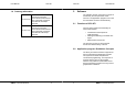
The configuration of the address space and
used interrupt channel is achieved by jumpers
on CPC-XTI. Their position on the board is
indicated in figure 1.
User Manual CPC-XTI
EMS Dr. Thomas Wünsche 19
DC/DC-
Converter
Processor
Controller
CAN 1
Controller
CAN 2
Flash-
ROM
CAN 1CAN 2
RAM
J1
18
J2
15
Figure 1: Jumper locations
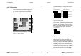
The base address is set with jumper bank J1.
The possible selections are listed in figure 2.
Jumper bank J2 determines the used interrupt
channel. The settings can be seen in figure 3
(IRQ 5 is set as an example). It is not allowed
to set more than one jumper on this bank.
Jumper J3 (optional) allows to supply + 12V
from the PC to the CAN on CPC-XTI card
configurations without galvanic decoupling. J3
may only be set if no other device supplies the
CAN power line and the PC has enough
capability on its +12V line. This feature does
not provide protections against overvoltage,
overload, short circuit or other error conditions.
The use of this option is in the resposibility of
the user.
CPC-XTI User Manual
20 EMS Dr. Thomas Wünsche
1
8
Bit 16
Bit 15
Bit 14
Bit 13
Bit 12
Bit 11
Bit 10
Bit 17
Address = 0C0000h + Jumper Value
Jumper installed Bit = 1, else Bit = 0
Jumper Allocation:
Sample Settings:
Address 0C8000h
Address 0D0000h
Address 0D4000h
Address 0DFC00h
Adress
Bit
Linear
Figure 2: Address settings
15
6
5
4
3
Jumper Allocation:
IRQ
line
IRQ 7
IRQ
IRQ
IRQ
IRQ
Figure 3: Interrupt settings