
User manual


3 Electrical Characteristics
3.1 Absolute Limiting Values
Any (also temporary) stress in excess of the
limiting values may cause permanent damage
on CPC-XTI.
Parameter Min. Max. Unit
Storage temperature –20 80 C
Operating
temperature *
060C
Voltage on the bus
connections
–30 30 V
Current across
ground connection
–1A
* Extended temperature range on demand
3.2 Nominal Values
Parameter Min Typ Max Unit
CAN
controller
clock
frequency
– 16 – MHz
Bus data
rate
– 10, 20, 50,
100, 125,
250, 500,
1000 and
others
– kBit/
s
User Manual CPC-XTI
EMS Dr. Thomas Wünsche 17
4 Operation Instructions
4.1 Connection Scheme
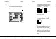
The CAN-interface-connector (D-Sub 9 male)
complies to CiA Standard DS 102-1. The pin
usage is detailed in the following table.
Pin 1 – Reserved by CiA
Pin 2 CAN_L CAN_L bus-line
(dominant low)
Pin 3 GND Ground
Pin 4 – Reserved by CiA
Pin 5 – Reserved by CiA
Pin 6 (GND) Optional ground,
internally connected
to Pin 3
Pin 7 CAN_H CAN_H bus-line
(dominant high)
Pin 8 – Reserved by CiA
(error line)
Pin 9 V+CAN Positive power supply
from CAN (not used by
default)
CPC-XTI User Manual
18 EMS Dr. Thomas Wünsche