
User's Manual

EMS Wireless Operator’s Manual
EkoLite II
38
C
C
NC
NC
NO
NO
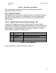
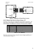
Pin 1: ALARM-1-NO
J26
Pin 2: ALARM-1-C
Pin 3: ALARM-1-NC
Pin 4: ALARM-2-NO
Pin 5: ALARM-2-C
Pin 6: ALARM-2-NC
Alarm 1
Alarm 2
Green Light (No Alarm Indicator)
Red Light (Alarm Indicator)
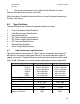
Typical application circuits
Audible Buzzer (Alarm Indicator)
General Circuit Topology
2 Amp Max Load Current
Figure 8: Application of Alarm Relay Contacts
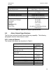
4.8.2.2 Master Hub External Alarm Relays, J27
Connector J27 provides user configurable external alarm connections. J27
alarm outputs are available on all EkoLite II Hubs with or without a master
control module. Pin definitions for connector J27 can be seen in Table 9.
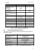
Pin Signal Description
1 V-ALARM +5 Volts Output for alarm
2 ALARM-OC Open-Collector Alarm Output
3 GND Signal Ground
4 Not Connected <No connection>
5 EXT-ALARM-1-IN TTL Alarm Input #1
6 EXT-ALARM-2-IN TTL Alarm Input #2
Table 11. J27 Connector
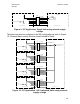
The alarm output can be driven using the internal voltage supplied by pin 1.
This can be seen in Figure 11.