
User's Manual

EMS Wireless Operator’s Manual
EkoLite II
17
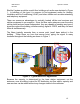
Each EkoLite II Hub can support up to eight Remotes. If more than eight Remotes
are required, up to 3 additional Hubs can be added allowing for a total of 32
Remotes.
1.2.2 Fiber
EMS recommends single mode 9/125 µm optical fiber for use in the EkoLite II
system. It is also recommended that a high quality SC/APC connector be used to
minimize reflections at the mating ends of the fiber. SC/APC connectors are
standard on both the Remote and the Hub. All connectors should be thoroughly
cleaned prior to each mating and plastic caps used to cover the connectors when
not mated. Dust and other contaminants can scratch and permanently damage
fiber connectors rendering them useless.
The maximum length for a fiber run is a function of the loss within the fiber itself
plus some margin for aging and other factors.
The maximum fiber loss (including connectors) for EkoLite II is 2.0 dB. This
correlates to roughly 2 km for a typical fiber such as Corning’s SMF-28.
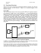
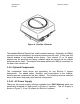
1.2.3 Remote Unit
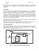
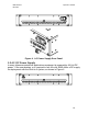
The remote is designed to convert the Fiber Optic Signals to/from RF and transmit
those signals to/from the Hub. Figure 3 is a functional diagram of the EkoLite II
remote. Figure 4 is a pictorial view of the remote.
EkoLite II
Remote
Antenna
+12 dBm DL
DL
+20 to +48 V DC Power
DL
UL
1310 nm
Duplexer
1310 nm
UL
Figure 3. EkoLite II Remote Unit Block Diagram.