
User's Manual

Preliminary Document Confidential EMS Wireless
Link2Cell
TM
-19
Manual
16
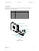
IMPORTANT: Before performing any maintenance or changing the position or location of
the unit, make sure power plug is removed from the 110 AC wall socket. Once the unit is
repositioned, the power should be plugged into the 110 wall socket, this will insure the unit is
set to maximum gain and performance.
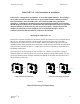
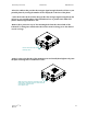
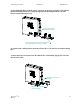
System Set Up Instructions:
-After installing unit, apply power and Link2Cell™ unit will automatically set up. The
system initialization will require 1 – 2 minutes for setup completion.
-Note: Since the Link2Cell™ is a broadband unit, it will improve the service for all
system providers with cell sites in the direction the donor antenna is positioned.
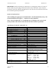
Specifications for Model: Link2Cell™-19
Downlink Operating Frequency, MHz 1930 to 1990
Uplink Operating Frequency, MHz 1850 to 1910
Downlink EIRP Transmit Power dBm 15
Uplink EIRP Transmit Power dBm 28
System Gain dB 40 to 79
Gain Flatness dB
+/− 2
Noise Figure dB
≤ 6
Spurious Output @ Rated Power
FCC Regulations dB
≤ -13
@Fc +/− 885 KHz (CDMA only) dBc ≤ 45
@Fc +/− 1.25 MHz dBc ≤ 26
2 tone @ -1 dBm each, DL dBc
≤ 60
1 dB Compression dBm UL 22, DL 22
IP3 dBm UL 41, DL 41
Operating Temperature, degrees C 0° to +50°
Power Source: (115 VAC) 9 VDC@ 1 amp, External AC to DC
Mechanical Dimensions, H x W x D, inches 14.25 x 14.25 x 6.0
MTBF hours 80,000
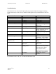
Indicators, Green LED Solid, Normal Operation
Red LED Flashing, Signal Overdrive
Solid, Auto Off, Contact Service Provider
Yellow LED
Flashing, No Signal Detected, ≤ 90 dB
Solid, Weak Signal, ≤ 85 dB
Automatic System Set Up Upon Power Up
System Gain Indications upon Power Up
For first 3 minutes
Green, Flashing during set up
Amber/Red ≥ 76 dB Solid
Amber ≥ 73 dB Solid
Red ≥ 70 dB Solid
Amber/Red ≥ 67 dB Flashing
Both OFF = 64 dB
Certifications, FCC, UL, CSA
*Meets or exceeds the EIA/TIA system requirements for
CDMA, TDMA or GSM system protocols.