
User's Manual

EMS Wireless Operator’s Manual
EkoLite II
31
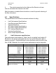
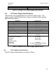
PARAMETER DOWNLINK UPLINK
Intermodulation
Output Carrier to Noise:
30kHz BW
200kHz BW
P
out
=+9dBm
≥64 dB
≥56 dB
---
---
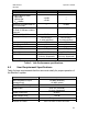
Sensitivity for 200kHz BW for
BTS S/N of 9dB
--- -98 dBm
Sensitivity for 1.25MHz BW
for E
b
/N
o
of 7dB and 14.4kHz
data rate
--- -111dBm
SFDR in 200kHz BW 53 dB 61 dB
Propagation Delay
<0.5 µs (RF) +
5 µs/km,typ (fiber)
<0.5 µs (RF) +
5 µs/km,typ (fiber)
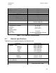
Impedance
50 Ω 50 Ω
Input/Output VSWR <1.5:1 <1.5:1
Hub RF Connector N-type N-type
Remote RF Connector SMA(f) SMA(f)
Optical Connector SC/APC SC/APC
Optical Fiber
9/125 µm (core/clad)
1310 nm, singlemode
9/125 µm (core/clad)
1310 nm, singlemode
Wavelength 1310 nm 1310 nm
Table 2. Link Performance specifications.
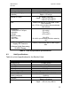
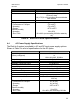
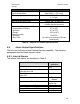
4.2 User Requirement Specifications
Table 3 shows requirements that the user must satisfy for proper operation of
the EkoLite II system.
PARAMETER USER REQUIREMENT
Max Composite RF Input
(damage level)
+30 dBm (downlink)
+10 dBm (uplink)
Max Optical Fiber Length 2 km
Optical Fiber
9/125 µm (core/clad)
1310 nm, singlemode
Optical Connectors SC/APC
Optical Return Loss
≥ 40 dB
Number of Optical Fibers Two per remote unit
Chassis AC Power 90 to 135 VAC or 184 to 264 VAC