
User's Manual

EMS Wireless Operator’s Manual
EkoLite II
23
(c) RF Spectrum analyzer
(d) Signal generator
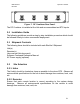
2.4 Power Supply Installation
If purchased, install the power supply and connect power to the Hub. An on-off
switch is located in the rear of the chassis and should remain in the off position until
the installation is completed. Before connecting the Hub or Remotes to the power
supply, apply AC power to the supply and verify the 48 V output with a Volt meter.
2.5 Single Hub Installation
To Install the Hub, locate it as close as possible to the Service Provider’s BTS.
Any distance between the BTS and Hub will result in unnecessary cable losses. It
is also very important to ensure that the composite RF Downlink power does not
exceed +20 dBm. Table 1 shows the maximum allowable power setting for each
carrier to arrive at a composite power of +20 dBm.
Number of Carriers Power Per Carrier
1 +20 dBm
2 +17 dBm
3 +15.2 dBm
4 +14 dBm
n +20 - [10log(n)] dBm/ch
Table 1. Power per carrier table
Note that each additional provider requires a reduction in carrier power to maintain
the maximum rated input power of +20 dBm.
• Using a Philips screwdriver and the provided screws, secure the Hub in
a standard 19” equipment rack near the BTS.
• Connect the Downlink RF Output from the BTS to the RF Input on the
Hub.
• Connect the RF Output from the Hub to the BTS Uplink port.
• Connect the power to the Hub.
• If the modem option was purchased and a dedicated phone line is
available, connect the RJ-45 phone jack.
• Log onto the Hub as user and follow the system initialization procedures.