
User's Manual
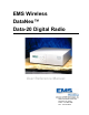
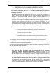

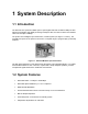

Table of Contents iv
DataNex EMS Wireless, DATA-20 Digital Radio
Table of Contents
1 SYSTEM DESCRIPTION .......................................................................................................................1-1
1.1
Introduction ..................................................................................................................................................... 1-1
1.2 System Features ............................................................................................................................................... 1-1
1.3 Typical Configurations.................................................................................................................................... 1-2
1.3.1 Data Rate and Interface ............................................................................................................................. 1-2
1.3.2 Standalone Operation ................................................................................................................................ 1-2
1.3.3 Hot Standby (Protected) Operation............................................................................................................ 1-3
1.4 Regulatory Notices........................................................................................................................................... 1-3
1.5 System Description (QAM)............................................................................................................................. 1-4
1.5.1 Introduction ............................................................................................................................................... 1-4
1.5.2 QAM Modulator/IF Upconverter............................................................................................................... 1-5
1.5.3 RF Upconverter ......................................................................................................................................... 1-6
1.5.4 Power Amplifier (PA) ............................................................................................................................... 1-7
1.5.5 RF Downconverter .................................................................................................................................... 1-7
1.5.6 QAM Demodulator/IF Downconverter ..................................................................................................... 1-8
2 INSTALLATION .....................................................................................................................................2-1
2.1 Unpacking ........................................................................................................................................................ 2-1
2.2 Notices............................................................................................................................................................... 2-1
2.3 Rack Mount...................................................................................................................................................... 2-2
2.4 Duplexer: Internal/External ........................................................................................................................... 2-2
2.5 Rear Panel Connections & Indicators ........................................................................................................... 2-3
2.6 Power Requirements ....................................................................................................................................... 2-5
2.6.1 Power Supply Card Slot Details ................................................................................................................ 2-5
2.6.2 AC Line Voltage........................................................................................................................................ 2-5
2.6.3 DC Input Option ........................................................................................................................................ 2-6
2.6.4 Fusing ........................................................................................................................................................ 2-6
2.7 Power-Up Setting............................................................................................................................................. 2-6
2.8 Data Interface .................................................................................................................................................. 2-8
2.8.1 4xE1/T1 MUX Channel Configurations.................................................................................................... 2-8
2.9 Hot Standby (Protected) Configuration ........................................................................................................ 2-9
2.9.1 Hot/Cold Standby Modes ........................................................................................................................ 2-10
2.9.2 Hot Standby Control using the TP64...................................................................................................... 2-11
2.9.3 Hot Standby Control with Single Unit..................................................................................................... 2-14
2.10 Site Installation .............................................................................................................................................. 2-15
2.11 Antenna/Feed System.................................................................................................................................... 2-16
2.11.1 Antenna Installation................................................................................................................................. 2-16
3 FRONT PANEL OPERATION ...............................................................................................................3-1
3.1 Introduction ..................................................................................................................................................... 3-1
3.2 Front Panel Operation .................................................................................................................................... 3-1
3.2.1 LCD Display.............................................................................................................................................. 3-2
3.2.2 Cursor and Screen Control Buttons ........................................................................................................... 3-2
3.2.3 LED Status Indicators................................................................................................................................ 3-3