
User's Manual
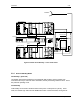

Installation 2-12
DataNex EMS Wireless, DATA-20 Digital Radio
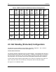
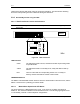
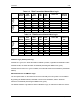
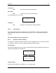
Table 2-3. TP64 Transmitter Master/Slave Logic
Selected
Master
TXA
Status
TXB
Status
TXA
LED
TXB
LED
Active TX TX Relay
Position
A OK OK GRN YEL A A
A OK FAIL GRN RED A A
A FAIL OK RED GRN B B
A-Master
Logic
A FAIL FAIL RED RED N/A A
B OK OK YEL GRN B B
B OK FAIL GRN RED A A
B FAIL OK RED GRN B B
B-Master
Logic
B FAIL FAIL RED RED N/A B
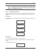
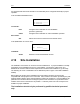
Table 2-4. TP64 Receiver Master/Slave Logic
Selected
Master
RXA
Status
RXB
Status
RXA
LED
RXB
LED
Active RX RX Data &
Clk
A OK OK GRN YEL A A
A OK FAIL GRN RED A A
A FAIL OK RED GRN B B
A-Master
Logic
A FAIL FAIL RED RED N/A None
B OK OK YEL GRN B B
B OK FAIL GRN RED A A
B FAIL OK RED GRN B B
B-Master
Logic
B FAIL FAIL RED RED N/A None
A-Master Logic (default power-up):
If RADIO A is “good”, the TP64 will remain in RADIO A position, regardless of RADIO B’s status.
If RADIO A fails, the TP64 will switch to RADIO B (assuming that RADIO B is “good”)
If RADIO A then returns to a “good” condition, the TP64 will switch back to RADIO A (the default
Master)
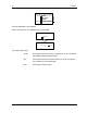
Manual Switchover to B-Master Logic
The front panel switch on the TP64 can be used to manually force the system to a new Master.
By pressing the RADIO B button, RADIO B now becomes the Master, and the TP64 will
switchover to RADIO B (assuming that RADIO B is “good”).
The default A-Master Logic will then switch to B-Master Logic, as outlined in Tables 2-3 and 2-4.