
User's Manual

Installation 2-6
DataNex EMS Wireless, DATA-20 Digital Radio
2.6.3 DC Input Option
An optional DC input power supply is available for the DATA-20; using high reliability, DC-DC
converter(s) capable of operation within the following input ranges (dependent upon nominal input
rating):
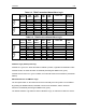
Nominal DC Input Operating Input Range
24 Volt: 20 – 28 VDC
48 Volt: 32 – 64 VDC
The DC input is isolated from chassis ground and can be operated in a positive or negative
ground configuration. The power supply module is removable from the unit and no high voltages
are accessible.
2.6.4 Fusing
For AC modules, the main input fuse is located on the switching power supply mounted to the
carrier PC board and the protective cage may be removed for access to the fuse.
For DC modules, all fusing is located on the carrier PC board.
Always replace any fuse with same type and rating. Other fuses are present on the board, and
are designed for output fail-safe protection of the system. All output fuse values are printed on
the backside of the PC board to aid in replacement.
NOTE: If a fuse does blow in operation, investigate the possible cause of the failure prior to
replacing the fuse, as there is adequate built-in protection margin.
2.7 Power-Up Setting
As shipped, the DATA-20 will radiate into the antenna upon power-up, THIS ASSUMES THAT
THE ANTENNA LOAD IS GOOD (LOW VSWR). If the VSWR of the load causes a high reverse
power indication at the PA, the red VSWR LED will light and the transmitter will cease radiating.
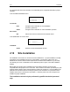
This is called the “AUTO” setting in the QAM RADIO CONTROL screen (see below).
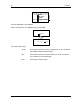
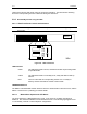
The LCD screen (“QAM RADIO TX CONTROL”) selects the power-up state and controls the
radiate function of the TX unit.
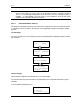
Go to the MAIN MENU: