
User's Manual

2-3 Installation
DataNex EMS Wireless, DATA-20 Digital Radio
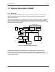
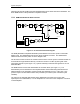
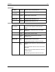
2.5 Rear Panel Connections & Indicators
Please refer to the Figure 2-2 for a pictorial of a typical product rear panel (internal duplexer).
Following is a descriptive text of the connections and LED indicators.
Figure 2-2.DATA-20 Rear Panel Connections
Power Supply:
Inputs: AC: Universal Input, 100-240V, 50/60 Hz; IEC 3
conductor
DC: 24v/48v (Isolated Input); 2 pin socket (custom)
Status LED: +12V: Green LED indicates +12 volt supply OK
+5V: Green LED indicates +5 volt supply OK
NMS Card
I/O Port: RS232 PC access; 9 pin D-sub (female)
Reset Switch: Activates hard system reset
Status LED: Green LED Indicates CPU OK