
User's Manual

IM 610179-1, Rev 02
08/25/06
Page 9
This unit will be installed by a professional installer using the appropriate anchors, etc. to
support a minimum of 30 lbs(actual weight of unit is 10 lbs) with four(4) #8 screws a minimum of
1 ¼ inch in length(not provided with unit) for the surface where the unit is being mounted in the
orientation shown located within 2.95 meters of the unit.
Standard hand/power tools possessed by any qualified installer are adequate for both installing
and removing the unit.
The power supply cord must not be attached to the building surface nor run through walls,
ceilings, floors, and similar openings in the building structure. The power supply cord must be
inserted in a standard receptacle.
CAUTION !
DOUBLE POLE / NEUTRAL FUSING
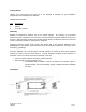
Select Mounting location of Donor directional antenna and orient toward the base station to
maximize signal level. For best performance this should be line of sight between the Donor
antenna and the base station antenna.
Alarms
All alarms are considered major since there are no field replaceable modules in the unit. All
alarms are indicated locally and immediately by the Alarm LED indicator blinking red. Once the
Alarm State has existed for 5 minutes, the Alarm LED will have a constant red indication.
Certain problems will result in the unit automatically shutting down after 5 minutes of sensed
failure. This is done by disabling the RF output stages in both the uplink and downlink signal
paths. Removing DC power from the unit for a period of 30 seconds or longer will reset the auto
shut down.
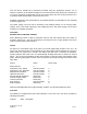
Failure Action Alarm Code
Alarm Cleared 0
Synthesizer Lock, Uplink Auto Shut Down 1
Synthesizer Lock, Downlink Auto Shut Down 2
Downlink RF Overdrive Auto Shut Down 3
Uplink RF Overdrive Auto Shut Down 4
No Downlink RF Detected* Alarm Only 5
Internal Voltage Failure Alarm Only 6
Low Current Draw Alarm Only 7
Keep Alive(1) Auto Shut Down 8
External Alarm Alarm Only 9
*Minimum detectable RF level is approximately -10dBm. Unit will alarm below this level.
Indicators
The EkoMini is equipped with three LED indicators on the end of the unit which provide the
following information:
Indicator State Description