
User's Manual

Preliminary Document
CI Wireless Inc. 11/19/99 7
Installation:
Note 1: qualified technicians should only perform Installation and system set up. The user is cautioned that
modification or changes to this device not expressly approved by the party responsible for compliance could void
the user’s authority to operate this equipment.
Note 2: Manufacturer’s rated output power of this equipment is for single carrier operation. For situations when
multiple carrier signals are present, the rating would have to be reduced by 3.5 dBm, especially where the output
signal is re-radiated and can cause interference to the adjacent band users. This power reduction is to be
determined by means of input power or gain reduction and not by an attenuator at the output device.
Note 3: This device complies with Part 15 of the FCC Rules. Operation is subject to the condition that this
device does not cause harmful interference.
Introduction
Eko-Mini is quick and easy to install, using a minimum set of common tools. This section will
provide the basic steps to performing the installation of EkoCel -Mini. Please read complete
instructions before beginning assembly.
Getting Started:
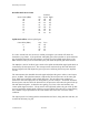
Unpack all of the boxes and insure all of the material is included for your installation
requirements and undamaged in shipment.
QTY Description
1 EkoCel -Mini
1 +9 VDC Power Module
1 AC Power Cord
4 Mounting Screws and wall inserts
1 Manual
1 Test Data, Factory
1 Optional, Telephone cable 6 ft.
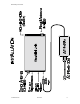
Mounting the Hardware:
-Mount the Mini Unit with the four mounting screws provided.
-Connect coaxial cables the Donor and Rerad ports.
-Connect primary power module to AC source and connect 9 VDC output to Mini DC Input.
-Optional connect telephone line to RJ11 jack.
Refer to attached drawing for any clarification.
Select Mounting location of Donor directional antenna and orientated toward the base station
to maximize signal level. For best performance this should be line of sight between the Donor
antenna and the base station antenna.
Select mounting location of Rerad antenna to provide maximum coverage while maintaining at
least 20 feet from normal usage if possible to reduce the possibility of overdrive.