
User's Manual

Preliminary Document
CI Wireless Inc. 11/19/99 6
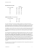
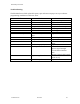
Uplink RF >-10 dBm
>-5 dBm
> 0 dBm
>5 dBm
>10 dBm
>15 dBm
>20 dBm
Over Drive
Downlink RF >-10 dBm
>-5 dBm
> 0 dBm
>5 dBm
>10 dBm
>15 dBm
>20 dBm
Over Drive
*No RF Uplink Detected; this is a normal state for the uplink RF path. The normal levels of
RF received and amplified from the subscriber unit may be below the –10 dBm detectable
level. A quick check can be made by getting within a few feet of the Rerad Antenna, while
watching the Uplink RF indicator.
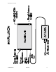
Primary Power
The Mini Unit operates on 9 VDC input power @ 6 Amps. This is supplied with a regulated
wall mount supply, which is UL, and CSA listed. These are available to operate on AC input
voltages of 90 to 260 VAC.
Donor Antenna
This input/output is connected to an antenna, which is directed at the desired cell site.
Rerad Antenna
This input/output is connected to an antenna, which is mounted in the desired area to be
covered. The antenna should be mounted at a location where adequate coverage is provided
for the area desired while minimizing the potential of subscriber units normally operating close
enough to overdrive the unit.
Serial Number
Each unit has a unique electronic serial number. This number is displayed on the decal on the
unit and is also displayed with the history log when using the modem interconnect.