
User's Manual

EMS Wireless
EMS Wireless EkoMini Manual
8
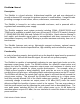
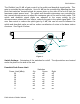
The EkoMini has 30 dB of gain control in the uplink and downlink signal paths. This
gain is controlled by two methods. Up to 14 dB can be controlled by adjusting the user
peak limit switches located behind an access plate on the side of the unit to limit the
maximum output power level. The uplink and downlink attenuators are controlled by
the internal microprocessor to adjust the maximum gain of the unit for both paths. The
uplink and downlink signal paths are adjusted to the same setting by the
microprocessor unless the user offsets, reduces the gain in the uplink signal path. The
user has control to reduce the uplink gain by 6 dB, this can be used to balance the
uplink and downlink paths as well as reduce contribution of noise to the base station
receivers. See Figure 1 below.
Figure 1.
Switch Settings. Orientation of the switches for on/off. The dip switches are located
under the plate on the side of the unit.
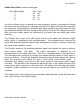
Downlink Peak Power Limit
Switches
Power Limit (dBm) Six Seven Eight
20 off off off
18 on off off
16 off on off
14 on on off
12 off off on
10 on off on
8 off on on
6 on on on
12345
678
1
23
45
678
OFF
ON
RESET
COVER PLATE
REMOVED