
User's Manual

EMS Wireless
EMS Wireless EkoMini Manual
17
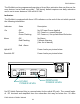
Select mounting location of Rerad antenna to provide maximum coverage while
maintaining at least a 20-foot spacing from closest cell phone usage if possible to
reduce the possibility of overdrive.
IMPORTANT: Before performing channel or amplitude adjustments on any unit, make
sure power is OFF.
System Set Up Instructions:
-During initial set-up, downlink signal must be presented to the unit.
-Apply Power after setting user switches and unit will automatically set up.
-Set Band Switches to desired Band for PCS or 3 dB roll off point for Cellular SW 3 &
4 (Preset at Factory to A or D depending on the Models BW 15 or 5 Mhz) (Cellular set
to Channel 338 B Band and Channel 329 A Band)
-Set UL gain offset as desired (Preset to 4 dB offset)
-Set DL RF Output Power to desired maximum Level (Factory Preset to full Power,
20 dBm Composite)
-Set Protocol selection Switch (Factory Preset to All Other, SW 5-OFF)
-For set up of optional remote alarming refer to software set up instructions.
Setting Up Remote Alarming
Alarm Code String Sent
The EkoMini will Page the Report Dial Out number and send the following
format:
Site location 00 Alarm code. Example: 9182736405005. The
"9182736405" portion is the Site Location if defined as all Digits and set
report name. "00" is the separator. 5 in this case is the alarm code. (See
section, Alarms, 5 is No Downlink RF Detected)
The unit is preprogrammed with the serial number and can be changed by
the user to indicate the site location. There is always an alarm code at the
end of the message after the separator designators 00. An alarm code of
“0” indicates no alarms exist or alarms cleared. The alarm message may
contain several alarm codes indicating several types of alarms are present.