
User's Manual
EMS Wireless
EMS Wireless EkoMini Manual
9
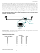
Uplink Gain Offset, reduces uplink gain
Gain Offset (dBm) One Two
0 off off
-2 on off
-4 off on
-6 on on
If a unit is initially set-up or moved from one location to another, pressing and holding
the reset switch a minimum of 5 seconds until the LED’s blink will restart the automatic
set up feature. If the peak limit and uplink gain offset switches are preset when the unit
is installed the EkoMini will first attempt to set itself up to the full RF output power of 20
dBm and then reduce power as instructed by the peak limit and uplink gain offset
switches.
The EkoMini has a total of 30 dB of gain control in the uplink and downlink signal
paths, which is controlled by the microprocessor. The microprocessor monitors the
uplink and downlink detected signal levels and adjusts the gain to prevent overdriving
the linear power amplifier circuits.
The EkoMini monitors the downlink-detected signal and adjusts the gain to achieve
rated output power, +20 dBm. The uplink attenuation is adjusted by the
microprocessor to the same gain level. Path loss is normally equal in both directions.
The microprocessor continues to monitor the detected output power on both paths to
prevent overdrive. Should the downlink detected power increase above the desired
level; the processor will reduce the gain in both uplink and downlink paths. A
subscriber unit getting very close to the rerad antenna, may cause uplink signal
overdrive. The processor will temporarily reduce the gain in the uplink (reverse) path
when uplink signal overdrive is sensed, which will reduce the coverage during this
condition. Proper placement of the rerad antenna will reduce the occurrence of this
condition.
The output power level setting and the maximum detected level, along with date and
time, are recorded in the history log file.