
User's Manual

CI Wireless Inc.
1211 Ira E. Woods Ave., Grapevine, TX 76051
57
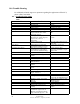
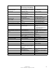
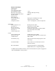
10.2 Understanding Setup and Alarms Information
Hub
Optical Receive
(Composite Alarms Optical Transceivers 1 to 4)
Laser Alarm
Communications Link R1
R2 (RF Modem link failure)
R3
R4
TX Lzr Power RF Input Power to Laser
TX Base Power RF Input Power from Base Station
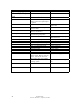
RF Up Link R1
R2 (As defined in Signal Gain over Optical Path Loss)
R3
R4
Down Link Power Out R1
R2 (Actual detected output power at remote as stated in
R3 dBm)
R4
Down Link Power Set R1
R2 (Last setting of output power made at remote)
R3
R4
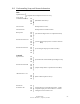
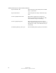
Controls
Up Link Gain R1
R2
R3 (Sets Attenuator to desired RF Up Link Signal Gain)
R4
Down Link Power dB R1
R2
R3 (Adjusts Output Power to specified Level in dBm)
R4
*Remote Power R1
R2
R3 (Main or Back Up Power select)
R4
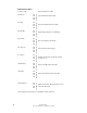
Down Link R1
Peak Power Set R2 Set Peak Power level for RF output power. Limits
R3 composite output power below this level. Default
R4 settings FCC licensed max levels