
User's Manual

CI Wireless Inc.
1211 Ira E. Woods Ave., Grapevine, TX 76051
22
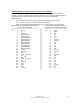
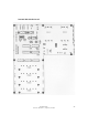
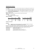
Terminal Strip
TS - 485 UNUSED
12 VDC/Out
U6
D5
Relay 1 NC
Relay 1 COM Hub Alarm*
Relay 1 NO
Relay 2 NC
Relay 2 COM Microcell (Remote) Alarm*
Relay 2 NO
24 VDC/IN
Ground
*Normally energized, de-energized in alarm state. Indicated states are alarmed condition.
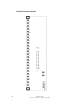
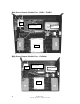
Attenuators
Outputs Connects to Up Link Combiner RF Inputs
AT 1 Out Remote Address 1 +/or 5
AT 2 Out 2 +/or 6
AT 3 Out 3 +/or 7
AT 4 Out 4 +/or 8
CAUTION
* These inputs must be connected to the proper laser modules serving
microcells (remotes) of the indicated address.
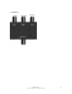
Inputs Connects to Optical Transceiver RF Out
AT 1 IN from Fiber Transceiver 1
AT 2 IN from Fiber Transceiver 2
AT 3 IN from Fiber Transceiver 3
AT 4 IN from Fiber Transceiver 4
Other
Fuse 24 VDC Input Fuse, 3 Amp
12 VDC System Circuit Fuse, 5 Amp