
User's Manual

CI Wireless Inc.
1211 Ira E. Woods Ave., Grapevine, TX 76051
21
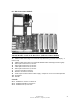
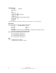
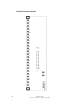
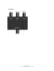
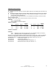
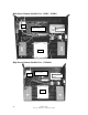
6.6 Hub Interconnect Module
700-1005 Board Located on the Base Plate (Hub Interconnect Module)
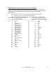
Input Connectors
J1
- Ribbon Cable Connecting to the Controller Top Board Ass’y, (nearest LCD display &
Power Lead)
J2
- Ribbon Cable Connecting to the Controller Bottom Board Assembly (nearest keypad)
J3
- Fiber Optical Transceiver 1, RF OUT
J4
- Fiber Optical Transceiver 2, RF OUT
J5
- Fiber Optical Transceiver 3, RF OUT
J6
- Fiber Optical Transceiver 4, RF OUT
J7
- 1.9 GHz TX Power In Detector
J8
- 800 MHz TX Power In Detector
J9
- Power Input 12 VDC from AC Power Supply *Jumper Pin 1 to 3 for 24 VDC Operation
J10
- RF Modem
J11
- RS 485
Controls
VR 1
-
Calibration 1.9 Detect TX Power In
VR 2
-
Calibration 800 MHz TX Power In
VR 3
-
Calibration RF Up Link Gain