
User's Manual
CI Wireless Inc.
1211 Ira E. Woods Ave., Grapevine, TX 76051
13
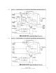
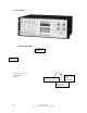
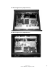
4.0 DESCRIPTION OF THE HUB UNIT MODULES
4.1
Fiber Optic Transceiver
The Fiber Optic Transceiver provides the RF signal transmission and reception
via the fiber optic cable between the hub and microcell units. Alarm monitor
outputs are provided to the control module to provide real time monitoring of the
operational performance. The down link transmitted optical signal is 1550 nm
wavelength and the up link received optical signal is 1310 nm wavelength. The
different optical wavelengths allow the addition of wave division multiplexing
(WDM) to any unit. This also reduces the requirement for maintenance spares in
mixed system.
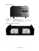
4.1b
Fiber Optic Master with Dual Receive and a Single Transmitter
This optical transceiver accomadates the additional up link receive path required
for Diversity Receive option. The unit has a single down link 1550 mm laser
(Channel C, RF In) and two receive photo diodes (Channel A Main Receiver and
Channel B Diversity Receiver) combined together with an internal Wave
Division Multiplexer (WDM) allowing single fiber operation. RF Modem uplink
path is on Channel A.
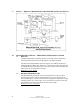
4.2
RF Modem
The RF Modem module provides several functions in the RF signal path. The
modem provides the data receive and data transmit path between the hub and the
microcell units with communication links being RS485. The data is transmitted
on a RF carrier on the down link path in the 460 to 512 MHz band and received
on the up link path on the same selected RF channel. These signals are coupled
with the carrier signals with a directional coupler or triplexer. The RF modem
receiver reports the RSSI level to the controller to calculate the RF and up link
optical path loss. The controller also uses this reading to adjust the up link
attennuator to the proper setting for desired carrier signal level.
4.3
RF Detector
The down link RF carrier level is monitored by the controller as part of the
closed loop gain control and auto set up system. This level is reported as Base
Station input RF power level and laser input level. The operator can view the RF
detected level as desired for maintenance, installation and system set up.
4.4
Splitter/Combiner
The Splitter/Combiner allows the input and output RF signals to the base station
to be split to 4 paths to serve the optional system capability to support up to four
remote microcell units. The hub will support the expansion of four fiber optic
transceivers. A splitter output on the down link is used to couple signal to the RF
detector and one up link combiner output is used to couple signal to the RF
modem.
4.5
DC/DC Converter
The DC to DC converter provides the required conversion of DC levels required
internal from the 18-36 VDC supply voltage provided by the user from the base