
User's Manual
CI Wireless Inc. 1211 Ira E Woods Ave 62
Tel: 817 416 0583 Grapevine, TX 76051
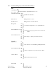
9.5.8 Up Link System Set Up for the System
Up Link system set up for the system: The gain at the remote is a fixed at maximum this
prevents system level changes from effecting the system noise figure at any optical path
loss up to 20 dB RF loss. Adding attenuation at the hub makes UL system level
adjustments. The RF modem detects the up link modem carrier RSSI level and
adjustments are made using this pilot carrier as a reference. (RSSI level is updated once
every 10 seconds).
Display
UL # Gain dB: XX dB (set to desired signal gain level)
Set desired Up Link Gain and press the Menu key. We suggest a level for RF UL 1
Detect between 4 dB and 6 dB. This will minimize system noise figure contribution
maintaining EkoCel specified performance of <6 dB noise figure. Repeat steps for
additional remote units.
System Set Up is Complete.
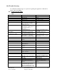
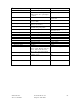
9.6.0 Calibration Table - U2
Remote RF Modem pilot level to Hub RF Modem RSSI
Refer to calibration tables provided with each unit OR Download tables Using terminal
mode at hub.
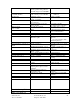
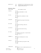
9.6.1 Calibration Table - U3
RF Input at Laser RF In. Tx 1.9Lzr Pwr: ,or Tx 800Lzr Pwr:
Refer to calibration tables provided with each unit OR Download tables Using terminal
mode at hub.
9.6.2 Calibration Table – U5
RF Output from PA at Remote Unit. DL # PA Detct:
Refer to calibration tables provided with each unit OR Download tables Using terminal
mode at hub.
Note: All values on Calibration Tables are in mV.