
User's Manual
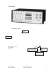
CI Wireless Inc. 1211 Ira E Woods Ave 13
Tel: 817 416 0583 Grapevine, TX 76051
5.4 Duplexer
The duplexer couples the down link transmitted signals and the up link received
signals to a common antenna output which allow band selective or full band
system operation.
5.5 Lightning Arrestor
The lightning arrestor is to provide maximum protection from the environment.
Throughput energy ≤0.5 µJ (8/20µs at 3kA). DC blocked for maximum
equipment protection. N/female connection to the RF input/output.
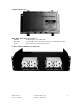
5.6 Power Amplifier Module
The power amplifier module provides amplification for the down link signals
which are coupled through a directional coupler from the fiber optic receiver. It
also provides for gain level setting with a FET attenuator on the input which is
voltage controlled by the controller. The system gain can be adjusted in <1 dB
steps by the controller. The output power is monitored via a directional
coupler/detector circuit on the output of the PA. The detected power reading is
sent to the control module and is used for auto system set up and monitoring of
power by the user for maintenace and manual adjustments.
The power amplifier module also contains a circuit, which monitors the base
plate temperature. Should the base plate temperature rise above a safe level
(75° C.) an alarm will be generated which is monitored and reported by the
control module. The power amplifier will also shut down until the base plate
temperature is reduced to 60° C. at which time the PA will turn back on.
Although the alarm will clear it will retain the status that a PA temperature alarm
was activated for maintenance personnel to review the cause.
Versions of Power Amplifiers:
1.9M - 3 watt Linear, 1.930 - 1.990 GHz
1.9R - 12 watt Linear, 1.930 - 1.990 GHz
800M - 8 watt Linear, 851 - 866 MHz or 869 - 894 MHz
5.7 Heater/Thermostat (Optional)
The heater provides a means to heat the enclosure to improve the performance at
lower temperatures and to extend the operating temperature range to –40° C.
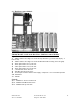
5.8 Microcell (Remote) Control Interface Module
The Microcell (Remote) Control interface module provides circuits to set units’
address and calibration controls for RF power and down link RF and optical loss.
The controller also monitors the enclosure ambient temperature and provides
electronic compensation for low temperature operation if required. The DC to
DC converter provides +5 VDC and –5 VDC for operation of the laser modules.
DC distribution to the controller, optical receiver, optical transmitter, and RF
modem is provided via this interface module.