
Operator's Manual

CI Wireless Inc. Installation of the CDR812
MirrorCell Select CDR812 Manual
Rev. X1 7-11
YY = Forward maximum transmit level for channel 1
N = Repeater’s channel 2
MM = Forward maximum transmit level for channel 2.
SET LVD 1 40 2 40 <enter>
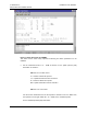
Typing STATUS will show that the channel number and gain settings have been
changed. The repeater now should be configured for operation.
11. The repeater should be turned off before connecting it to the antennas. Once
connected, the repeater can be turned on. The output power of the repeater should
be monitored on the test port. The test ports are 30dB couplers; thus if an output
power of 40dBm (2W) is desired, the power measured at the test port should be
10dBm. The attenuation of the repeater should be decreased until the desired output
power is achieved.
7.7 Optimization
Now that the repeater is providing the desired output power, the system needs to be
optimized. The search window and neighbor lists of the donor base station should be
reviewed. Verify the pilot search window parameters are properly set to compensate for
filter group delays in the repeater. The repeater uses highly selective Surface Acoustic
Wave (SAW) filters, which have a group delay of 11 microseconds. Since the propagation
delay of free space is 5.4 microseconds per mile, the delay is “equivalent” to two miles of
free space propagation.
The search window of the donor base station may need to be increased depending on
the distance from the repeater to the donor base station. For example, if the repeater is 3
miles from the donor base station, and the desired coverage area of the repeater is 2
miles (for a total of 5 miles):
(5 miles) * (5.4 µsec/mile) + 11 µsec (delay in the repeater) = 38 µsec
The donor BTS pilot search window would need to be at least 38 microseconds for call
activation to take place.
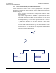
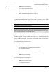
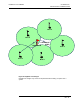
The neighbor lists of the donor base station and the base stations surrounding the area
served by the repeater need to be adjusted. For example, in Figure 19 a repeater
extends the coverage of BTS1 to a new area. BTS1 is now neighbors with BTS4 and
BTS5, whereas without the repeater, BTS1 is neighbors with just BTS2 and BTS3. Thus
BTS4 and BTS5 must be added to BTS1’s neighbor list, and BTS1 must be added to
BTS4’s and BTS5’s neighbor lists. A drive test of the coverage area should be performed
to verify the final setup.