
Operator's Manual

Installation of the CDR812 CI Wireless Inc.
MirrorCell Select CDR812 Manual
7-4
Rev. X1
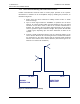
Antenna isolation can be measured once the donor and server antennas have been
mounted at their initially desired location. Isolation measurement is important in properly
setting up a repeater.
4. The repeater gain can be set to at least 10dB below the figured measured
above. (The antenna isolation must be at least 10dB greater than the
repeater gain.) For example, if the antenna isolation measured is 90dB, the
repeater gain should be set for no more than 80dB.
5. If isolation is not great enough (ie, if more gain is required), you can try either
of the following:
a. Separate the antennas by a greater distance.
b. Mount some type of external shielding between the antennas, such as a
mesh screen, an ice shield, or grounded metal plate.
7.5 Repeater Mounting and Installation
The following recommendations should be adhered to for enhanced repeater
performance.
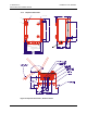
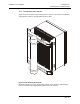
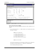
1. The repeater comes standard with wall mount brackets as shown in Figure
16. The brackets attach to the repeater with eight M8x1.25 thread bolt
screws, included in the shipment.
2. The repeater should be mounted so the heatsink avoids direct sunlight. This
will help improve the lifetime of the repeater.
3. Mount the repeater upright so that the connectors are on the underside. This
will help prevent a buildup of moisture inside the repeater.
4. The repeater is equipped with 7/16” DIN (or N-type as an option) antenna
connectors. Connectors are located at the bottom of the unit. A protective
cover is included with the repeater to prevent unauthorized access to the
connectors. The cover can be installed or removed only from the inside of the
unit.
5. Ensure that adequate room has been allocated for the bending radius of the
cables. Refer to the cable manufacturer’s specifications for the allowable
cable-bend radius.
6. Ensure that adequate room is allowed for the opening and closing of the
repeater door. See Figure 16 for dimensions of the repeater.