
Operator's Manual

CI Wireless Inc. Description of the Control Module
MirrorCell Select CDR812 Manual
Rev. X1 6-3
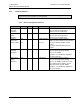
SET CHA X YYY <enter>
where X = channel within the repeater and YYY = the CDMA channel number. The
channel can be set only to channels within your system’s band of operation.
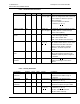
6.5 Quick Commands
Three quick commands are available with the function keys:
• F1: Help Menu
• F2: Shows a list of the last ten entered commands
• F3: Shows the Status screen.
6.6 Command Log
The control module stores the last ten commands that have been entered. The F2 button
brings up these commands. Use the up and down arrow keys to read off these stored
commands. The right and left arrow keys can then be used, along with backspace and
clear, to edit the commands as needed.
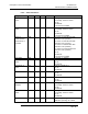
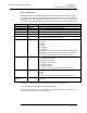
6.7 Configuring the External Alarms
The external alarms can be configured active-low or active-high, so the alarm is given in
either the absence or presence of applied power. Input voltage can range from 12 VDC to
24 VDC. For configuration, use the following command:
SET EXT BC <enter>
where B refers to pin 1 and C refers to pin 2.
B or C = 0 means the absence of voltage is normal,
B or C = 1 means the presence of voltage is normal.
The alarms are laid out so that pin 1 is read from EX1 and pin 2 is read from EX2.
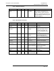
6.8 LED Indicators
The LEDs on the control module are tri-colored, where the illuminated colors mean:
• GREEN: Repeater is functioning properly
• AMBER: User is logged in to the control module
• RED: Repeater is not functioning properly
Note: Depending on the alarm configuration, the door alarm may go off a number of
seconds after the door has been opened; in this case, the LED will change from Amber to
Red.