
Operator's Manual


CI Wireless Inc. Description of the Major Modular Components
MirrorCell Select CDR812 Manual
Rev. X1 2-1
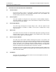
2 DESCRIPTION OF MAJOR MODULAR COMPONENTS
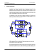
2.1 Channel Modules
Each channel module consists of a preamplifier, a baseband downconverter with SAW
(Surface Acoustic Wave) filters, a baseband upconverter, and a post amplifier. The
module includes power level control functionality.
2.2 Power Amplifiers
The power amplifiers are designed for an output power of 12.5W (41dBm) composite .
The power amplifiers are designed to meet IS-95 standards for Adjacent Channel Power
Ratio (ACPR) or spectral regrowth.
2.3 Power Supply Module
The power supply is designed for an input voltage of 105 – 130 VAC. Options for 230
VAC and 24 VDC are available. In addition, the AC input is equipped with a surge
suppression filter.
2.4 Duplex Filter
The transmit and receive antennas are combined with duplex filters operating in the PCS
frequency band. The filter consists of comb-line cavity bandpass filters, which provide
excellent isolation against out-of-band signals.
2.5 Status and Control Module
The status and control module enables monitoring and control of the repeater. This
module determines the status of all channel modules and identifies all failure conditions.
When an alarm occurs, the module can send a message to a PC over a serial data link.
The PC connection is over a serial port through an RS232 interface to a VT-100 series
terminal. The status and control module sends and receives channel and amplification
data on the addressed channel modules when connected to a modem.
Monitoring and control is possible through the MirrorCell Element Manager (MEM) using
a modem connection. The MEM is not accessible with a direct hard-line connection to the
status and control module.
2.6 LNA Module
The LNA (Low Noise Amplifier) module consists of a low noise amplifier to provide the
initial gain for a good noise figure.