
User's Manual
CI Wireless Inc. 1211 Ira E Woods Ave 68
Tel: 817 416 0583 Grapevine, TX 76051
R3 detected, millivolts)
R4
* Not equipped in all units prior to manufacture dates of 8-1-98
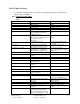
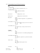
Remote Unit Alarms
Optical receive
Laser Alarm
Laser temperature Alarm
PA Temperature Alarm +75°C
RF Power Output Alarm 6 dB below RF output setting
Enclosure Temperature Alarm 0 to 70°C
Intrusion Alarm Door
Primary Power
Battery Back up
Low TX Input Power Input signal <15 dBm @ Laser Input
Output Power Output power drop <10 dB
Temperature Alarm <10 or > 160 degrees F, Cabinet Temperature
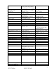
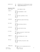
Information
Down Link Power Out RF Output Power, dBm
TX Power In Input Power to Laser In dBm
RF Up Link Detect RF Up Link signal Gain
Up Link Gain Control Last Up Link Gain Setting command at Hub
TX Power In Power From Base Station, dBm
Cabinet Temperature Degrees C
Control
Down Link Power dB Set RF output power in dBm
Up Link Gain dB Sets Up Link Signal Path Gain to desired level
* Remote Power Main or BBU
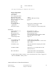
Alarm History Log Scholl last 100 alarms, displaying Date, Time
Alarm Type
Alarm Reset Menu Select remote to reset alarms (F4 resets all
alarms all remotes)
RS 232 Port Mode Activates RS 232 Port as Terminal Mode
Modem Mode, None - Programming Mode
# Additional R5 - R8 Remote Alarms, controls and information if system is equipped for
dual band 800 MHz/1.9 GHz operation.
Additional Features for Future Product Releases