
User's Manual

CI Wireless Inc. 1211 Ira E Woods Ave 30
Tel: 817 416 0583 Grapevine, TX 76051
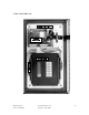
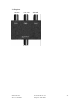
7.7 System Interconnect
700-1001 Board (2 required) Located on Control Module
700-1001 Board Assembly is the Ribbon Cable adapter interface to the controller module.
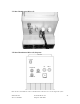
Caution: if replacing the 700-1001 interface, it has 24 interconnecting pins to the terminal strip
and the terminal strip actually has 25 pins on both sides.
Note when installing:
Pin 1 connects to 12VDC on the side nearest the display/power LED
Pin 1 connects to C2B on the side nearest the keypad
Refer to 700-1004 board assembly for proper interconnect to each assembly.
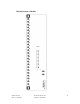
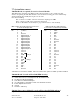
Ribbon Cable Assembly 700-1001 Connected Ribbon Cable Assembly 700-1001
To Controller Display Side Connected to Controller Key Pad Side
Pin 1 12 VDC * Pin 1 C2B -
2 K 2 C2B +
3 Ground 3 RX +
4 Digital Output 1 4 RX -
5 Digital Output 2 5 TX +
6 Digital Output 3 6 TX -
7 Digital Output 4 7 Ground
8 Digital Output 5 8 Ground
9 Digital Output 6 9 D7
10 Digital Output 7 10 D6
11 Digital Output 8 11 D5
12 Digital Output 9 12 D4
13 Digital Output 10 13 D3
14 Unused 14 Unused
15 Unused 15 Unused
16 NO 16 + 5
17 COM Relay 2 17 Ground
18 NC 18 U1
19 NO 19 U2
20 COM Relay 1 20 U3
21 NC 21 U4
22 U EXP 22 U5
23 DAC 23 U6
24 A/D + 24 Ground
25 A/D - 25 D1
26 Ground 26 D2
* Illustrated on controller as 24VDC, however controller has option for 12VDC operation installed.
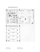
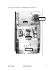
700-1002 Board Located on Heat Sink(EKO-1.9 only)
Input Connectors
J1 - J3 DC Interconnect, located Duplexer/AC-DC Module Panel
J2 - 12 VDC From AC Power Supply
J3 - 13.6 VDC From External DC Input
J4 - J3 on Board Ass’y 700-1004 Located on Controller Door Panel
J5 - Power Amplifier Connection
J6 - Unused
J7 - 12 VDC to LNA Ass’y
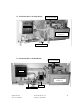
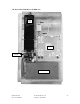
700-1003 Interconnect Module Located on Fiber Optic/RF Modem Panel
Input Connectors