
User's Manual

CI Wireless Inc. 1211 Ira E Woods Ave 71
Tel: 817 416 0583 Grapevine, TX 76051
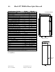
• Remove Fiber Optic/RF Modem Panel
1. Disconnect Fiber Optic cables and carefully place where they will not be
damage
2. Disconnect RF cables from couplers, 2 each.
3. Remove 15 pin ribbon cable from J4 on 700-1003 Interconnect board
assembly on panel
4. Remove 4 Panel Mounting screws
5. Panel will now lift out of unit
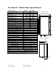
• Disconnect RF Cable from Duplexer, RX output
• Remove 4 mounting screws securing LNA Module
• Unplug DC Input from 700-1002 Interconnect assembly J7
• Lift LNA Module from Unit
• Remove Filter RF cables and reinstall replacement unit
• Reinstall LNA Module by reversing the procedure
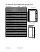
Replacement of any Module on the Fiber Optic/RF Modem Panel
• Turn Off and Disconnect Power from the Unit
• Remove Fiber Optic/RF Modem Panel
1. Disconnect Fiber Optic cables and carefully place where they will not be
damage
2. Disconnect RF cables from couplers, 2 each.
3. Remove 15 pin ribbon cable from J4 on 700-1003 Interconnect board
assembly on panel
4. Remove 4 Panel Mounting screws
5. Panel will now lift out of unit
• Remove and replace defective module on panel
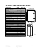
Replacement of Duplexer or AC-DC Module
• Turn Off and Disconnect Power from the Unit
• Remove Fiber Optic/RF Modem Panel
1. Disconnect Fiber Optic cables and carefully place where they will not be
damage
2. Disconnect RF cables from couplers, 2 each.
3. Remove 15 pin ribbon cable from J4 on 700-1003 Interconnect board
assembly on panel
4. Remove 4 Panel Mounting screws
5. Panel will now lift out of unit
• Duplexer - Remove 5 mounting screws from the back of panel and reinstall
replacement assembly
• AC-DC Module
1. Remove 4 screws securing cover
(con’t on next page)
2. Remove 4 screws inside securing unit to panel