
User's Manual
CI Wireless Inc. 1211 Ira E Woods Ave 52
Tel: 817 416 0583 Grapevine, TX 76051
Section 9. Installation
INSTALLTION OF THE EKOCEL 1.9 FIBER OPTIC MICROCELL:
NOTE 1: Installation and system set up should only be performed by qualified technicians. The user is
cautioned that modification or changes to this device not expressly approved by the party responsible for
compliance could void the user's authority to operate this equipment.
NOTE 2: Manufacture's rated output power of this equipment is for single carrier operation.
For situations when multiple carrier signals are present, the rating would have to be reduced by 3.5 dBm,
especially where the output signal is re-radiated and can cause interference to the adjacent band users. This
power reduction is to be determined by means of input power or gain reduction and not by an attenuator at
the output device.
Note 3 :This device complies with Part 15 of the FCC Rules. Operation is subject to the condition that this
device does not cause harnful interference.
9.1 Introduction
EkoCel is quick and easy to install, using a minimum set of common tools. This section
will provide the basic steps to performing the installation of EkoCel. Please read
complete instructions before beginning assembling.
9.2 Getting Started
Unpack all of the boxes and insure all of the material is included for your installation
requirements and undamaged in shipment. instructions before
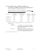
List of Basic Equipment:
Hub Unit, 24 Vdc
Microcell Unit, 100-220 Vac
Additional Optional Hardware:
WDM- Hub Panel with WDM
WDM installed in Microcell Unit
Fiber Jumper cables, 4 each, 1 meter length
Hub AC Option- AC power supply installed in unit
Expansion Unit Control Cable
Battery Back Up Unit for Microcell Unit with interconnect Cable
Determine and secure additional material required, base station interconnect coaxial
cable, antenna, coaxial cable, fiber optic jumpers, etc.
Slave remote units will require two coaxial cable jumpers and one control cable.
9.3 Mounting Hub Hardware
-Mount Hub unit and secure in base station cabinet or another 19 inch EIA cabinet.
-Connect Base station transmit and receive cables.
-Connect primary power, 24 Vdc or optional 115 VAC.
-Connect fiber Optic cables.
-Wave Division Multiplexer (WDM) Option.
Mount WDM assembly directly above or below the Hub Rack assembly.