
User's Manual

CI Wireless Inc. 1211 Ira E Woods Ave 31
Tel: 817 416 0583 Grapevine, TX 76051
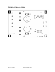
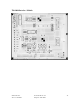
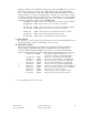
J1 - Fiber Receive Ribbon Cable Connection
J2 - Fiber Transmitter Ribbon Cable Connection
J3 - RF Modem Ribbon Cable Connection
J4 - J4 on Board Assembly 700-1004 Located on Controller Door Panel Connection
Jumpers
Normal Operation with Fiber Transmitter Model AC221T
Jumper Pins 1 to 6
10 to 5
3 to 4
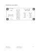
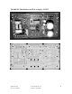
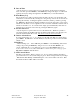
700-1004 Control Interface Located on Door
Input Connectors
J1 - Controller Connection with 26 conductor ribbon cable from LCD display side and Power Led
of controller
J2 - Controller Connection with 26 conductor ribbon cable from the Key pad side of the controller
J3 - 10 Conductor Ribbon Cable Connection to 700-1002 Board Assembly J4, located on Heat
Sink, between Power Supply & PA
J4 - 15 Conductor ribbon Cable Connection to 700-1003 Board assembly J4, located on Fiber
Optic / RF Modem Panel
RS-485- Cables to bulk head “control” Connector on base of the remote.
Jumpers
SW 1 - SLAVE ENABLE
SW 2 - Address Enable 5 through 8
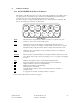
Address Jumpers
Voltage* Voltage*
SW Address Adjust Setting SW Address Adjust Setting
3 R - 1 none <0.7 VDC 3 5 VR5 3.7 VDC
4 R - 2 VR2 1.75 VDC 4 6 VR2 4.7 VDC
5 R - 3 VR3 2.4 VDC 5 7 VR3 5.5 VDC
6 R - 4 VR4 3.0 VDC 6 8 VR4 6 VDC
* Monitor Test Point 1
Controls
VR 1 - Calibration for PA detected output power, see calibration tables.(Test Point 2)
VR 6 - Calibration RSSI, DL optional/RF loss (Test Point 3)
800 MHz or 1.9 GHz remotes may be configured as Master or Slave units. Units are configured
at factory normally with the differential being. Master remote is equipped with Fiber Optic RF
modem panel and the controller interface module assembly is different for each unit.
700-1004-X1X 1.9 GHz Units address 1 - 4
700-1004-X2X 800 MHz units address 5 – 8
700-1004-X3X 1.9 GHz Expansion (slave) unit address 1 – 4
700-1004-X4X 800 MHz Expansion (slave) unit address 5 - 8