
Operating instructions


REV.9/28/05 Page 7 of 8 Part #17810
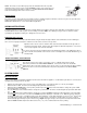
• If the receiver beeps when the ON button is depressed on the wall transmitter they are communicating.
• If the receiver does not beep when the ON
button is depressed on the wall transmitter, you will need to teach the receiver the
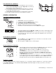
code of the transmitter. This is done by holding the LEARN
button down on the receiver (NOTE: The black slide Button covers
the LEARN access hole when installed), and at the same time depress the ON button on the wall transmitter. A change in the
beeping pattern, at the receiver indicates the transmitter’s code has been programmed into the receiver.
5. Make sure the wall transmitter is within the 15’-20’ range of the receiver.
6. Positioning of the receiver is important. If the receiver is “enclosed” in a metal surround, the operation of the receiver may be
affected as noted below. Reposition the receiver to improve operating range. It is suggested that a heat shield be installed to
protect the receiver from extreme heat. If the receiver is “enclosed”
in a metal surround, this can:
• Cause the RF signal to get lost and not communicate with the receiver.
• Cause the working distance to be shorter than normal.
NOTE
: A receiver located in an area, where the ambient temperature inside the case exceeds 130
0
F, will cause THERMO-
SAFETY feature to cut in, requiring you to reposition the receiver to stop the warning beeps, and to “reset” the receiver’s operation.
7. Due to handling and shipping of the unit, handling or dropping of the wall transmitter by the customer, and heat conditions to the
receiver, some units may need an occasional frequency adjustment. This adjustment is made to improve the communication and
operating distance between the transmitter and the receiver. See RECEIVER ADJUSTMENT.
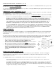
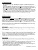
RECEIVER ADJUSTMENT – RECOMMENDED ADJUSTMENT
NOTE: The black slide button covers the ADJ access hole when installed.
A. To adjust at the receiver, use a small slotted screwdriver. Turn the adjustment screw counter-clockwise
about 5 degrees or a maximum of 1/8 turn. This should correct the distance problem.
B. If that does not correct the problem, return adjustment screw to original position and then turn adjustment
screw clockwise.
This adjustment is like tuning your radio. If you keep turning the adjustment screw, in either direction, you will go past the proper setting
(tuning).
SPECIFICATIONS
BATTERIES: Wall Transmitter 6 – 2ea. (CR2032) 3.0 volt lithium button cell batteries
Remote Receiver 6V –4ea. AA 1.5 Alkaline FCC ID No.’s: transmitter –(K9L TS-R-2A); receiver – (K9L 3301RX)
Operating Frequency: 303.8MHZ Canadian IC ID No.’s: transmitter – (2439A-TSR2A) receiver – 2439A-3301RX
FOR TECHNICAL U.S. INQUIRIES
CANADIAN INQUIRIES
SERVICE, CALL: 888/672-8929 or 877-472-3923
260/459-1703
Website: skytechsystem.com
MANUFACTURED EXCLUSIVELY BY SKYTECH II, INC
FCC REQUIREMENTS
NOTE: THE MANUFACTURER IS NOT RESPONSIBLE FOR ANY RADIO OR TV INTERFERENCE CAUSED BY
UNAUTHORIZED MODIFICATIONS TO THIS EQUIPMENT. SUCH MODIFICATIONS COULD VOID THE USER’S
AUTHORITY TO OPERATE THE EQUIPMENT.
Limited Warranty
This REMOTE CONTROL SYSTEM is warranted for 12 months from the date of purchase or installation to the original
purchaser to be free from defects in materials and workmanship. Damage to the SYSTEM caused by accident, misuse,
abuse, or installation error whether performed by a contractor, service company, or owner, is not covered by this
warranty. Seller will not be responsible for labor charges and/or damage incurred in installation, repair, and replacement
or for incidental or consequential damages. Batteries and any damage caused by them are not covered by this warranty.
Some states, provinces, and nations do not allow exclusion or limitations of incidental or consequential damages, so the
above limitations or exclusions may not apply. This warranty gives you specific legal rights. You may have other rights
that vary by state, province or nation.