SPA Installation and Directions of Use EMPV-SPA3528
Content Warnings........................................................................................................................................................... 1 I. USA Balboa Control System Instructions .................................................................................................. 2 CNBP501X Tech Sheet.......................................................................................................................... 2 Basic Functions Setup.............................
■Warnings: Please read the following instructions before operation and installation, which is a safety guaranty to SPA users. 1. The system must be installed by qualified technicians, switch for electricity leakage should be installed at a place convenient to be controlled or operated. 2. Reliable grounding protection for the SPA is a must, if not, we won’t take responsibility for the bad grounding! 3.
30. The bearing of the water pumps may get stuck after this SPA hasn’t been used for a long time, so the water pumps may not working when pressing the water-pump buttons on control panel. If the water pump not working because of water bearing get stuck, then you can notice that no water current through jets or no suction- force in the skimmer.
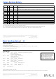
System Revision History Part # EPN Date Originator Changes Made 56582 56583 56584 4195 01-15-14 BWG BP501G3 initial draft. Adds GFCI Trip (but not GFCI Automatic Test). Updated to latest software version, adding topside-intergrated bba™ support. ZT000148 4467 02-18-15 Customer Spin off custom version of BP501G3 without 2-Speed Pump 2, and adding simplified menus version of eash Setup, and with new default Setup. 56746 4467 04-01-15 Customer Add two new reminders. Release to production.
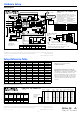
Hardware Setup Wiring Diagram CNBP501X PN 56849-02 MOVE WIRE TO CONNECT J2O TO J13 FOR BLOWER IN SETUPS 2, 3, 7 & 8 J5 (A1-A4) AUX 11-22-16 F2 3A 250V J19 J18 K7 J100 J101 J108 J22 J45 GND J29 VAC J28 AUX FRZ SENSOR B SENSOR A 5.5 kW HEATER W1 TORQUE RANGE FOR HEATER CONNECTIONS: 30 TO 35 IN. LBS.
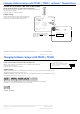
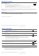
Changing Software Setups with TP800 / TP900 / spaTouch™ Menued Panel Test Menu Access (S1, Switch 1 ON) Service Technician ONLY. DANGER! HIGH VOLTAGE WILL BE ACCESSIBLE! SERVICE TECHNICIAN ONLY! While the system is running, move DIP Switch 1 (on S1 on the Main circuit board) to ON. The system will enter Test Mode. Moving DIP Switch 1 to OFF will exit Test Mode. Software Setups Under the TEST Menu, the Setup screen will allow changing the Setup from 1 to any number established by the Manufacturer.
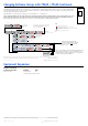
Changing Software Setups with TP600 / TP400 Continued Again, You will have 1 minute to complete the setup change after you manually exit Priming Mode. Immediately after exiting Priming Mode, press this sequence of buttons: Warm*, Light, Warm, Warm, Warm, Warm. Continue to press Warm until the diplay shows the Setup Number (S-01, S-02, etc.) you want to switch to. When the correct setup number is showing, press Light once, and the system will reset, using the newly-selected Setup from that point on.
DIP Switch Functions Fixed-fuction DIP Switches 1 A1 Test Mode (normally Off). A2 In “ON” position, add one high-speed pump (or blower) with Heater. A3 In “ON” position, add two high-speed pumps (or 1 HS Pump and Blower) with Heater. A5 In “ON” position, enables Special Amperage Rule B. See Special Features section under Configuration Options for functionality with your system. In “OFF” position, enables Special Amperage Rule A.
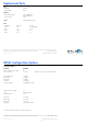
Replacement Parts PCBA: Main PCBA: Expander PCBA: 56851-02 551537 HEATER(s): Plug + Click Heater Kit: 58306 5.5kW 800Inc 58303 4.0kW 800Inc Temp Sensor Kit: 53605 CABLES: FUSES: Part Number Amperage Location 30A 3A 3/10A 10A F5, F1 (Expander) F2, F4 F6 F3 30136 20600 21581 30122 21302 Jumper 120V Heater Manufactured under one or more of these patents. U.S.
BP501 Configuration Options Temperature Features Feature Default Temperature Display °F Options Increment °C, °F All temperatures must be specified in °F. The system converts °F to °C dynamically. If Celsius is required for default settings, choose a desired °C value that (after rounding) corresponds to a Fahrenheit value.
BP501 Configuration Options Reminder Features Feature Default Reminders Shown* Yes Yes, No N/A Check pH 7 Days See Reminder Period Note 1 Days Check Sanitizer 7 Days See Reminder Period Note 1 Days Clean Filter 7 Days Test GFCI 60 Days See Reminder Period Note 1 Days Drain Water 90 Days See Reminder Period Note 1 Days Change Cartridge OFF Clean Cover 90 Days See Reminder Period Note 1 Days Treat Wood OFF See Reminder Period Note 1 Days Change Filter 120 Days Check Ozone (
TP800 Panel Configuration Button Layout Table Feature # Setup 1 Setup 2 Setup 3 Setups 4 & 11 Setup 5 A1 N/A N/A N/A N/A N/A A2 Jets 1 Jets 1 Jets 1 Jets 1 Jets 1 A3 Jets 2 Jets 2 Blower Jets 2 Light 1 A4 Jets 3 Blower Light 1 Light 1 Invert A5 Light 1 Light 1 Invert Invert Undefined A6 Invert Invert Undefined Undefined Undefined A7 Undefined Undefined Undefined Undefined Undefined A8 Undefined Undefined Undefined Undefined Undefined Undefined Undefined
TP600 Panel Configuration Button Layout Table Button # Setups 1 & 6 Setups 2 & 7 Setups 3 & 8 Setups 4, 9, 11 & 12 Setups 5 & 10 1 Jets 1 Jets 1 Jets 1 Jets 1 Jets 1 2 Jets 2 Jets 2 Blower Jets 2 Undefined 3 Jets 3 Blower Invert Invert Invert 4 Up Up Up Up Up Light 1 5 Light 1 Light 1 Light 1 Light 1 6 Down Down Down Down Down LED 1 Jets 1 Jets 1 Jets 1 Jets 1 Jets 1 LED 2 Jets 2 Jets 2 Blower Jets 2 Undefined LED 3 Light 1 Light 1 Light 1 Light 1 Li
BP501 Configuration Options Auxilliary Panel Features on Bank 1* Feature Default Aux Button A1 Jets 1 Aux Button A2 Jets 2 Aux Button A3 Jets 3 in Setups 1 & 6 Blower in Setups 2, 3, 7 & 8 Undefined in Setups 4, 5, 9 & 10 Aux Button A4 Light *Bank 1 consists of J5 on the Main Circuit Board. Aux Connection Splitter PN 25257 may be required. Buttons that are assigned to equipment that is not defined in a Setup will not do anything in that Setup. Manufactured under one or more of these patents. U.S.
II. Description on Using Parts 1. Heater/Thermostat 1) Normal starting up time is 4-8 hours 2) SPA Thermostat cannot be heated by man in the air, or there will be danger. If there is something wrong in operation, professional servant is a must to prevent the risk of electricity leakage. 2. Air pump Normal working time is 15-30 minutes (air pump shall not be working continuously over 120min., because it may overheated the whole part or shorten service life ).
4) Change the core paper filter half a year once, depends on the high quality of water, lifetime of paper filter can be properly extended. 5) Change a new paper filter, take out a new one and tear out the package of the paper core and put it inside the filtration bucket. 6) Match the paper core correctly inside and screw it down in sequence, then put the cover of filtration bucket on top.
4) Remove the water-return unit and nozzle for cleaning and removing dirt. 5) Do not frequently wipe the gold and chrome plated parts (do not contact it with organic solvent). 6) Please keep blunt and knife away from the surface, and butt or the things over 60 degree should be away from that too. 7) One time to check button of electricity leakage every month. 8) Make frequent checks on the electrical wires, buttons, connectors always to see if they are bitten by rats or worms.
3. Filter water pump is damaged. Constant temperature 1. Thermostat is damaged; effect is unavailable 2. Power supply is unavailable. 3. Filter is jammed.