
Manual

DCC2 User Manual
AES on ST glass input
Also with this link the DCC2 can be operated in either clock master or clock slave mode.
In master mode an optical cable can be used for the clock connection between DCC2
and your transport instead of a BNC cable. This will keep the DCC2 galvanically
separated from the transport. But a BNC cable for the clock can also be used.
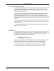
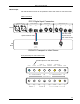
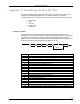
Cable connections:
AES/EBU INPUTS WORD CLOCK I/O
IN IN
OUT OUT
DSD INPUTS
S/PDIF INPUTS
COAX
21
TOS ST BNCLR
PUSHPUSH
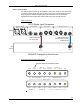
OPTICAL
CLOCK
IN
ST OPTICAL
DATA OUT
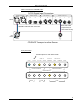
DCC2 Digital Input Connectors
CD/SACD Transport or other Source
DCC2
CD
Deck
Optical cable with
ST connectors
Optical clock cable
(required only for clock
master mode)
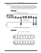
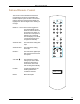
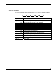
Front panel setup for clock master mode:
NARROW
WIDE
INVERTED
48 KHZ
44.1 KHZ
LOCK CLOCK
COAX TOS STSTBNCRCA
XLR
INPUT SELECT
AES
PCMDSDANLG
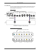
ANALOG OUTPUTCLOCK CONTROL
DIGITAL BWBASE FS
MUTE
POLARITY
EXT
Set this option for clock slave mode !
12