DCC2 DIGITAL CONTROL CENTER USER MANUAL Version 1.
DCC2 User Manual DCC2 Digital Control Center The DCC2 is a stereo D/A converter with built-in pre-amplifier that evolved from EMM Labs’s acclaimed converter and pre-amplifier systems that have been used worldwide in professional recording studios to master some of the finest recordings in both CD and SACD releases. The D/A section provides conversion from a wide variety of digital input formats to analog audio, and the pre-amp section provides 2 analog inputs and 1 analog output.
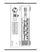
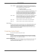
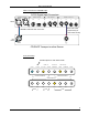
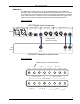
L R 2 BAL UNBAL R COAX RCA L TOS S/PDIF INPUTS ANALOG LINE INPUTS PUSH PUSH XLR PUSH PUSH AES/EBU INPUTS emm Labs ST R BNC R BNC DSD L IN ST ANALOG LINE OUTPUT L DSD INPUTS RCA PCM COAX OUT IN ST L REMOTE SYSTEM ANALOG PREAMP OUTPUT R OUT TOS ANALOG OUTPUT WORD CLOCK I/O AES INPUT SELECT BASE FS POLARITY DIGITAL BW 44.
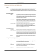
DCC2 User Manual Function Switches and Indicators Power The main power switch is on the back of the unit. The chrome power button on the front is a momentary switch that toggles the operation between power on and power save mode every time the user pushes it. During the power save mode the remote control and all front panel functions become inactive. Clock Control Section LOCK: This indicator is lit when the unit detects valid clock at the selected digital audio input.
DCC2 User Manual PCM – AES/EBU: Selects PCM digital input from the XLR inputs. Sample rates up to 96kHz are supported. For sample rates of 88.2kHz and 96kHz there are 2 configurations that are commonly used: 1) one cable for 2 channels 2) 1 cable for each channel (total of 2 cables) If 1 cable is used it needs to be plugged into AES/EBU INPUT 1, and if 2 cables are used both inputs 1 and 2 have to be connected. In either case the DCC2 will automatically detect if the digital input is running at 44.
DCC2 User Manual Basic Operations and Input Connections Memory after powerup and during operation After about 10 seconds after no button has been pushed and the volume has not been changed, the DCC2 memorizes its momentary setup in permanent memory for later retrieval after the next powerup. It will be recalled immediately after the unit is turned on. Each individual input selection will keep its last configuration and volume setting before powerdown.
DCC2 User Manual Clock Master and Clock Slave Modes The DCC2 provides 2 basic ways for how to connect an audio source to it, such as a CD transport: clock master and clock slave modes. Master / slave is in reference to who provides the clock signal to the D/A conversion process and who receives an external clock as a guide signal to lock to. In clock master mode the DCC2 generates and provides the clock to the D/A conversion process and also to the CD transport.
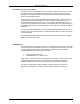
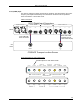
DCC2 User Manual Cable connections for AES/EBU input: DCC2 Digital Input Connectors AES/EBU INPUTS PUSH 1 PUSH S/PDIF INPUTS DSD INPUTS WORD CLOCK I/O 2 COAX TOS ST L BNC R IN IN OUT OUT DCC2 BNC clock cable (required only for clock master mode) AES/EBU cable with XLR connectors CD Deck BNC CLOCK IN AES/EBU DATA OUT CD/SACD Transport or other Source Front panel setup: Set this option for clock slave mode ! EXT LOCK CLOCK BASE FS 44.
DCC2 User Manual EMM OptiLink This EMM Labs proprietary link is used for the best performance with a EMM Labs transport system. The cables used are standard ST glass (multimode). The link consists of 2 connections, one for data and one for clock. If the DCC2 is operated in clock master mode a third connection is necessary, which can be established with a ST glass optical cable as well to maintain the galvanic separation between transport and DCC2.
DCC2 User Manual Coax (SPDIF) input This link can operate for sample frequencies up to 96kHz. The DCC2 detects the correct frequency and adjusts automatically. Also with this link the DCC2 can be operated in either clock master or clock slave mode.
DCC2 User Manual TOSLink input Also with this link the DCC2 can be operated in either clock master or clock slave mode.
DCC2 User Manual AES on ST glass input Also with this link the DCC2 can be operated in either clock master or clock slave mode. In master mode an optical cable can be used for the clock connection between DCC2 and your transport instead of a BNC cable. This will keep the DCC2 galvanically separated from the transport. But a BNC cable for the clock can also be used.
DCC2 User Manual Infrared Remote Control The remote control included with the DCC2 provides many functions for the EMM Labs CDSD transport system as well. The functions that are relevant to the DCC2 specifically are highlighted in blue rectangles in the drawing on the right. DISPLAY – DCC2: This function toggles the front panel display on the DCC2 on and off.
DCC2 User Manual Specification Output Line Level with 0dBfs signal on AES/EBU inut XLR balanced: RCA unbalanced: +12.55dBu / +10.35dBv / +3.3V +8.1dBu / +5.95dBv / +1.98V Pre-amp Output Level with 0dBfs signal in AES/EBU input Max. volume (99) XLR balanced: +18.4dBu / +6.47V RCA unbalanced: +13.95dBu / +3.
DCC2 User Manual Appendix A: Serial Remote Control (RS-232) The DCC2 is equipped with a 9-pin RS-232 connector for system remote control via a serial cable (not provided by EMM Labs). The cable should be non-crossed for connections between a PC and the DCC2. The parameters and settings for this link are: • • • • • 19,200 baud 8 bits 1 stop bit no flow control no parity bit Commands to DCC2 All commands sent to the DCC2 consist of 3 ASCII characters followed by a .
DCC2 User Manual Status info from DCC2 The DCC2 sends back 4 Bytes terminated with a whenever any status changes.