
Instructions
42
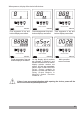
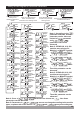
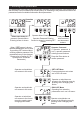
“rU” RevisionÞ
Revisionnumber
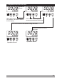
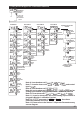
SSRDriverandDigitalOutput
Module(EMO ,EMO )-910 -920
SSRDriverandDigitalOutput
Module(EMO ,EMO )-910 -920
RelayOutput
Module(EMO )-900
RelayOutput
Module(EMO )-900
0/4...20mA CurrentOutput
Module(EMO )
Z
-930
0/4...20mA Current
OutputModule(EMO )
Z
-930
AnalogInputModule
(EMI ,EMI ,EMI
orEMI )
-910 -930 -940
-950
DigitalInputModule
(EMI )-900
DigitalInputModule
(EMI )-900
Thereisnomodulein
Module-1socket
Thereisnomodulein
Module-2socket
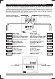
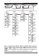
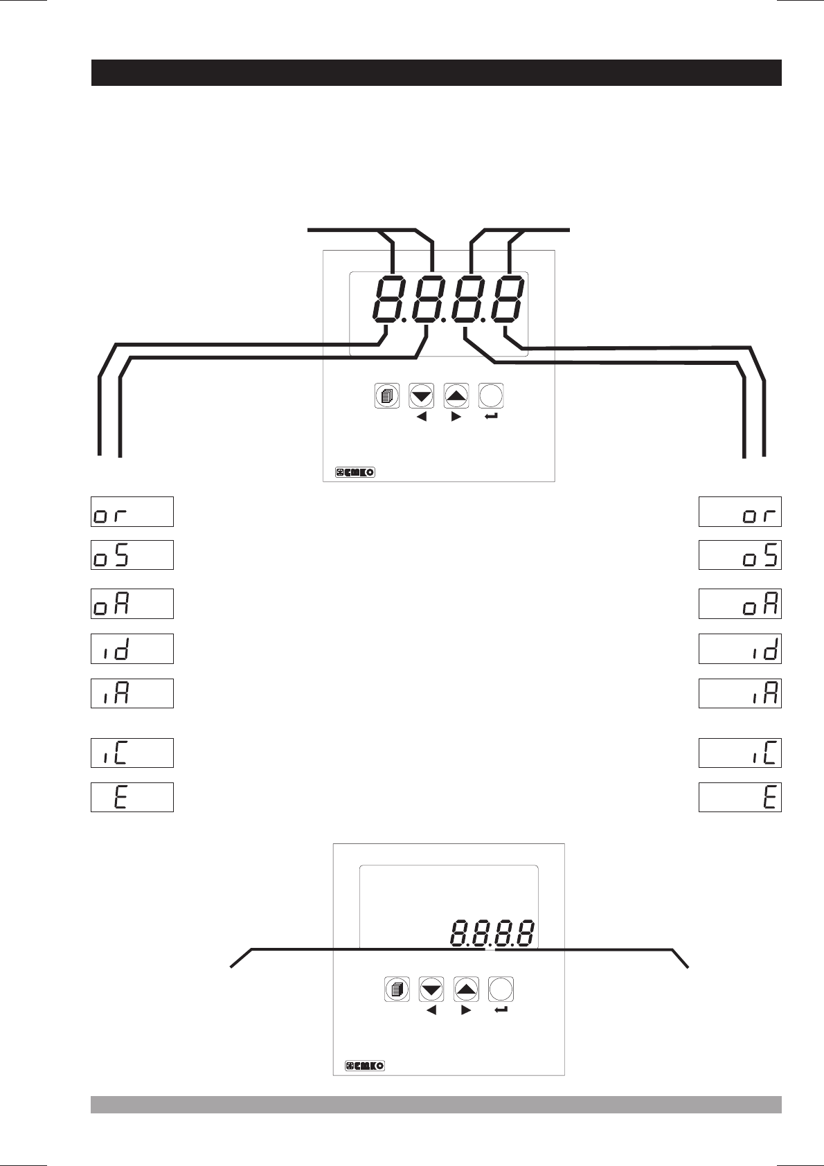
There are two sockets for plugging optional modules to the . These modules are
recognized by the automatically.
Module definiton codes and how to observe these codes of optional modules in
Module-1 and Module-2 socket are explained below :
device
device When the power is applied to the device all led indicators
and display segments are momentarily illuminated for testing. Software revision number of the
controller on the bottom display and module definition codes on the top display are momentarily
illuminated.
OptionalInput/Output
modulecodeforModule-1
OptionalInput/Output
modulecodeforModule-2
7.2ObservationofOptionalModulesandSoftwareRevisionontheDisplays
AnalogInputModule
(EMI ,EMI ,EMI
orEMI )
-910 -930 -940
-950
0...5 A CTInput
Module(EMI )
V
-920
0...5 A CTInput
Module(EMI )
V
-920
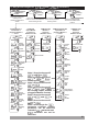
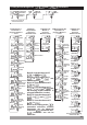
°C
°F
V
Remote
SV
AT
AUTO
MAN
RAMP
O1
O2
O3
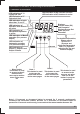
ProcessController
ESM-9950
SET
°C
°F
V
Remote
SV
AT
AUTO
MAN
RAMP
O1
O2
O3
ProcessController
ESM-9950
SET