
Instructions


72
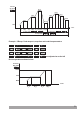
Max.50mA
TC
Pt-100
0-20mA Z
0to50mV
0to10V
Z
Z
1 2 3 4 5 6
MODULE-1 MODULE-2
7
8 9
10 11 12
13 14 15 16 17 18
19
20 21
22 23 24
M
~
N
L
5A@250V V
OUTPUT-3
CNCNO
100...240V V 50/60Hz
V V
RelayOutputModule
EMO-900
5A@250VV
NO
C
NC
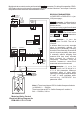
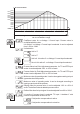
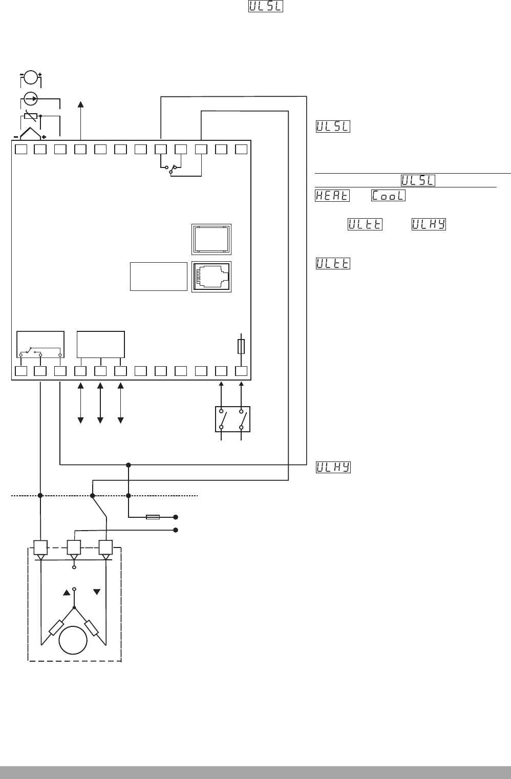
MotorizedValveControl
ElectricalWiringDiagramfor
ESM-9950.1.20.1.1/01.00
Input/Output
Module-2
Opening
Relay
Max.5A T
Fuse
V
Motorized valve control can be performed with parameter. For doing this operation, EMO
Relay output module must be plugged in Module-1 socket. Module-1 and output-3 controls
the position of the valve with motorized valve control.
-
900
MOTORIZEDVALVE
SensorSupply
Voltage
Output-3
Closing
Relay
UniversalProcess
Input
Closing
Common
Opening
Valve
Supply
Input
Opening
Closing
Communication
Module
(RS-232(standard)/
RS-485(optional))
Power
Supply
Switch
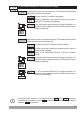
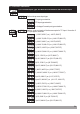
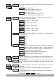
RELEVANT PARAMETERS:
In PASS OPEr or PASS tECH (run
LýSt) menu page ;
Þ
parameter : I t c a n b e
adjusted from 0,1 to 5,0. Unit is %. It
is % of Ultt parameter. Minimum
movement steps of valve while
opening or closing are determined as
% ratio. If valve oscillates while
c o n t r o l l i n g , I N C R E A S E t h e
parameter value!
Parameter : It defines how to
perform the motorized valve control
with the device.
or
In PASS tECH GEnn COnF menu
page and parameters
are shown.
If motorized valve control is activated
by selecting the parameter
Þ
parameter : I t c a n b e
adjusted from 5 to 600. The unit is
“second”.
It defines after how many seconds
valve is completely opened. For
determinig the parameter correctly,
close the valve manually. Be sure that
valve is closed completely, then open
it manually without stopping and
measure that how many seconds
hav e passe d for ope ning it
completely. Parameter must be
entered measured value+5%of
measured value and as second.
Note-1
Fuse
Note-1 :There is an internal 33R fusible flameproof resistor
in 100-240 V 50/60Hz
There is an internal 4R7 fusible flameproof resistor in
24V 50/60Hz , 24V
W
W
V
V Z
24V 10%Z ±