
Instructions


Out3Menu
47
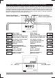
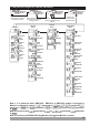
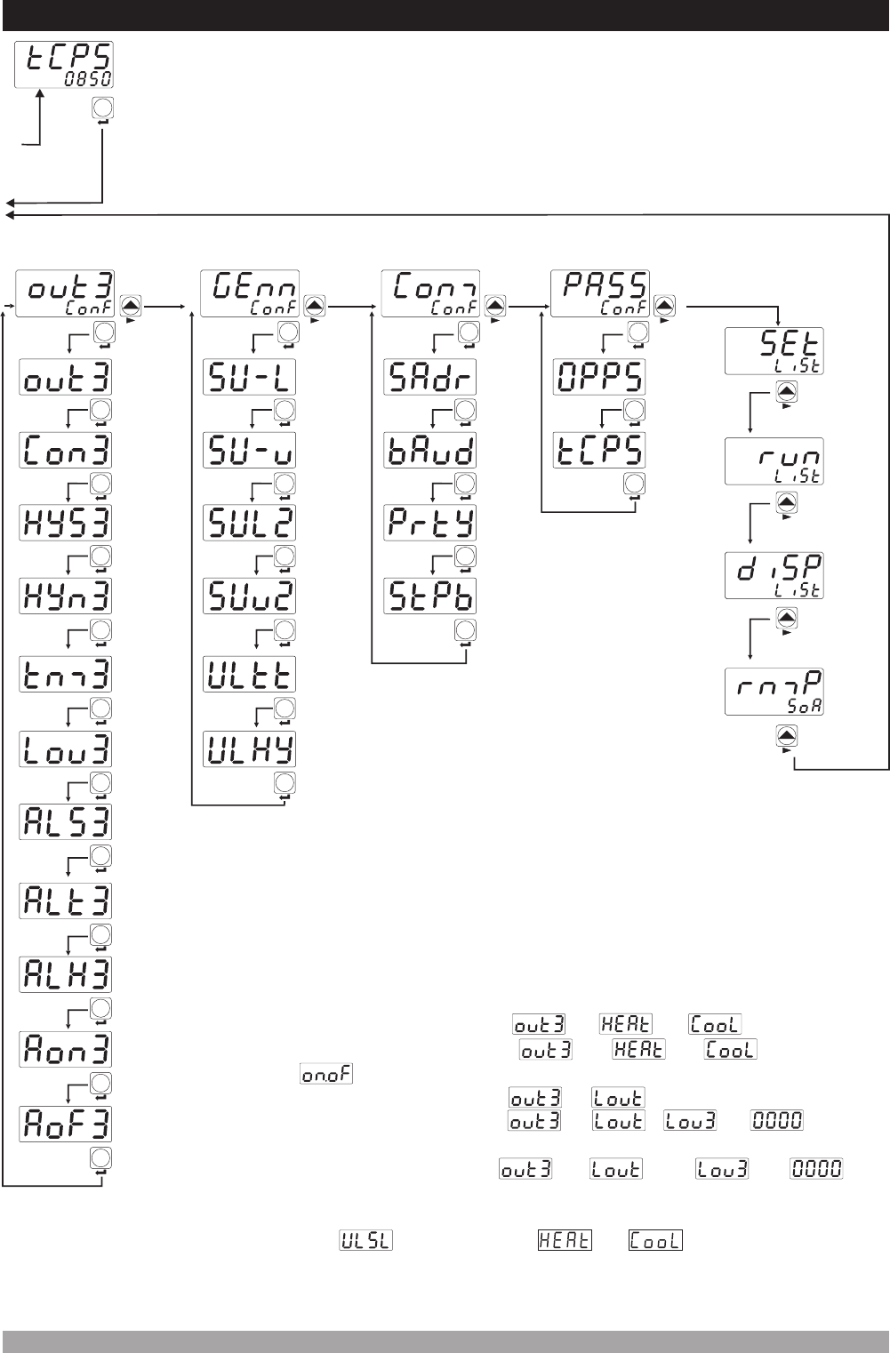
7.5Easy AccessDiagramforTechnicianParameters
SET
Technician
Password
Entering
Screen
Confirmthe
password
withSET/OK
button
SET
Hysteresis
Operation
Type
Minimum
on-time
Out3
Logic
Output
Measurement
InputSelection
for AlarmOut3
Output
Function
Selection
Control
Algorithm
Out3
Hysteresis
Value
SET
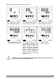
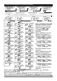
Note-6
SET
Note-7
SET
Note-8
Note-7
SET
Note-7
SET
SET
Note-9
SET
Out3
Alarm
type
Note-10
SET
Alarm3
Hysteresis
Value
Alarm3
OnDelay
Time
Alarm3
Off
Delay
Time
Note-10
Note-10
Note-10
SET
SET
SET
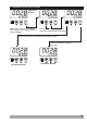
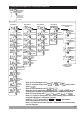
GennMenu
SET
2nd
Sensor
SetScale
UpLimit
Motorized
Valve
Travel
time
Motorized
Valve
step
Setscale
LowLimit
Setscale
UpLimit
2nd
Sensor
SetScale
LowLimit
SET
SET
Note-11
SET
Note-11
SET
Note-12
Note-12
SET
SET
CommMenu
PassMenu
SET SET
Stopbit
selection
Slave
Address
Operator
Password
Baud
Rate
Technician
Password
Parity
selection
SET SET
Note-13
SET SET
SET
SET
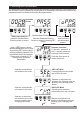
Operatormenusare
entered.
Set
Menu
RunList
Menu
Display
Menu
Ramp/
Soak
Menu
Note-13
Note-13
Note-13
Itturnstothe
beginningofthe
menulist
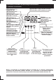
°C
°F
V
Remote
SVAT
AUTO
MAN
RAMP
O1
O2
O3
°C
°F
V
Remote
SVAT
AUTO
MAN
RAMP
O1
O2
O3
°C
°F
V
Remote
SVAT
AUTO
MAN
RAMP
O1
O2
O3
°C
°F
V
Remote
SVAT
AUTO
MAN
RAMP
O1
O2
O3
°C
°F
V
Remote
SVAT
AUTO
MAN
RAMP
O1
O2
O3
°C
°F
V
Remote
SVAT
AUTO
MAN
RAMP
O1
O2
O3
°C
°F
V
Remote
SVAT
AUTO
MAN
RAMP
O1
O2
O3
°C
°F
V
Remote
SVAT
AUTO
MAN
RAMP
O1
O2
O3
°C
°F
V
Remote
SV
AT
AUTO
MAN
RAMP
O1
O2
O3
Note-6: It can be observed if is or
Note-7: It can be observed if is or and control
type is
Note-8: It can be observed if is
Note-9:It can be observed if is , is and an
analog input module is plugged in Module-1 or Module-2 socket
Note-12:Ifparameterisor,thenthese
parameterscanbeobserved.
Note-13: Please refer to the Section 7.4 Operator Parameters easy
access diagram.
Note-10: It can observed if is and is
Note-11: It can be observed if one of the analog input module is
plugged in Module-1 or Module-2 socket.