
Instructions


SensororTransmitter
SupplyVoltage
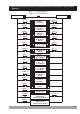
Output-3
StandardRelayOutput
TC
Pt-100
15
1 2 3 4 5 6
MODULE-1 MODULE-2
CATII
P/N: ESM-9950
Y
c
7
8 9
a
Communication
Socket
10 11 12
13 14 15 16 17 18
19
20 21
22 23 24
Max50mA
0to20mA Z
0to50mV
0to10V
Z
Z
5A@250V V
OUTPUT-3
CNCNO
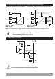
Universal
ProcessInput
(TC,RTD, Voltage/Current)Z
i
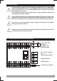
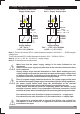
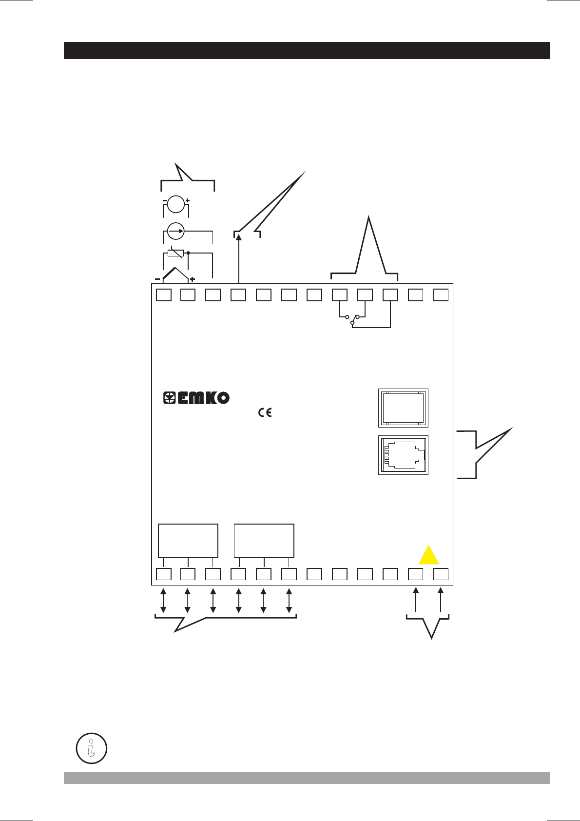
3.2ElectricalWiringDiagram
Electrical wiring of the device must be the same as ‘Electrical Wiring Diagram’
below to prevent damage to the process being controlled and personnel injury.
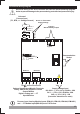
c
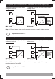
SupplyVoltageInput
100-240V (- )50/60Hz
24V (- 50/60Hz-6VA
24V (-
(Itmustbedeterminedinorder)
V
V
Z
15%;+10%
15%;+10%)
15%;+10%)-6W
-6VA
OptionalInput/OutputModuleTerminals
Relay,SSRDriver,DigitalorCurrent
OutputModule
Digital, Analogand CT
InputModules
V
Process input, Analog Module Inputs (EMI-910, EMI-930, EMI-940, EMI-950 )
and are in CAT II class.VCT Module Input (EMI-920)
24V 10%Z ±