
Instructions
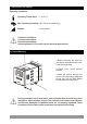
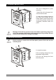
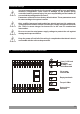
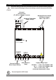
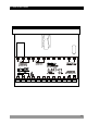
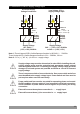
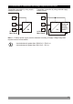
Table Of Contents
- Page 1
- Page 2
- Page 3
- Page 4
- Page 5
- Page 6
- Page 7
- Page 8
- Page 9
- Page 10
- Page 11
- Page 12
- Page 13
- Page 14
- Page 15
- Page 16
- Page 17
- Page 18
- Page 19
- Page 20
- Page 21
- Page 22
- Page 23
- Page 24
- Page 25
- Page 26
- Page 27
- Page 28
- Page 29
- Page 30
- Page 31
- Page 32
- Page 33
- Page 34
- Page 35
- Page 36
- Page 37
- Page 38
- Page 39
- Page 40
- Page 41
- Page 42
- Page 43
- Page 44
- Page 45
- Page 46
- Page 47
- Page 48
- Page 49
- Page 50
- Page 51
- Page 52
- Page 53
- Page 54
- Page 55
- Page 56
- Page 57
- Page 58
- Page 59
- Page 60
- Page 61
- Page 62
- Page 63
- Page 64
- Page 65
- Page 66

3.4 Connection of Device Supply Voltage Input
16
Supply voltage range must be determined in order. While installing the unit,
supply voltage range must be controlled and appropriate supply voltage
must be applied to the unit. Controlling the supply voltage range prevents
damages in unit and system and possible accidents as a result of incorrect
supply voltage.
There is no power switch or fuse on the device. So a power switch and a fuse
must be added to the supply voltage input. Power switch and fuse must be
put to a place where user can reach easily.
c
Power switch and fuse must be two poled for seperating phase and neutral.
On/Off condition of power switch is very important in electrical connection.
On/Off condition of power switch must be signed for preventing the wrong
connection.
External fuse must be on phase connection in V supply input.
External fuse must be on (+) line connection in Z supply input.
c
c
c
Note-1 :There is internal 33R W fusible flameproof resistor in 100-240 VV 50/60Hz
There is internal 4R7 W fusible flameproof resistor in 24VV 50/60Hz , 24VZ
Note-2 : “L” is ( + ) ,” N” is ( - ) for 24V Z supply voltage
Universal Supply
Voltage Connection
100 - 240 VV
(-15%;+10%) 50/60Hz
Supply Voltage
23
N L
24
N
t 1
o
e-
Y
Power
Supply
Switch
c
a
External
Fuse
(1 A V T)
Low Voltage 24 VW
Supply Voltage Input
24VV (-15%;+10%) 50/60Hz
or 24VZ (-15%;+10%)
23
L
24
Y
c
a
External
Fuse
(24V V : 1 A V T)
(24V Z : 1 A Z T)
Note-2
N
Supply Voltage
N 1
ot
e
-
Power
Supply
Switch